Search

Search all blog posts here.

Search This Blog

Thursday, May 30, 2013

Wheel Bearing Spacers

My front and rear wheel bearings were shot and the spacers were not correct either. Finding a set of bearings and seals was actually a bit of challenge. The bearings are HD part number 9052 or Timken Race LM 11910 and Timken Bearing LM 11949. We did some crossover work and the parts at NAPA as BR2 for the bearing and race. The seals were also a trick. The front uses a skinny version(I lost the number already.) The front uses fatter version(Federal Mogul 204020)

I didn't get as many pictures as I usually do on this effort, because I had help from Ed and Columbus. I really wasn't in the good mood after all the parts chasing on a Sunday afternoon to get everything. Then Ed being broke down halfway between my house and his house the next Sunday afternoon. Columbus did help remove and replace the front races and that was a lot of work for sure.

All that to get down to business. When axle nut is torqued down, the spacer should allow have 0.004 to 0.018 inches of movement of the Timken-style bearings according to book, but I'm told you want something closer to that 0.004 inch. This inspection and measurement should be taken with the bearings dry and not packed with grease.

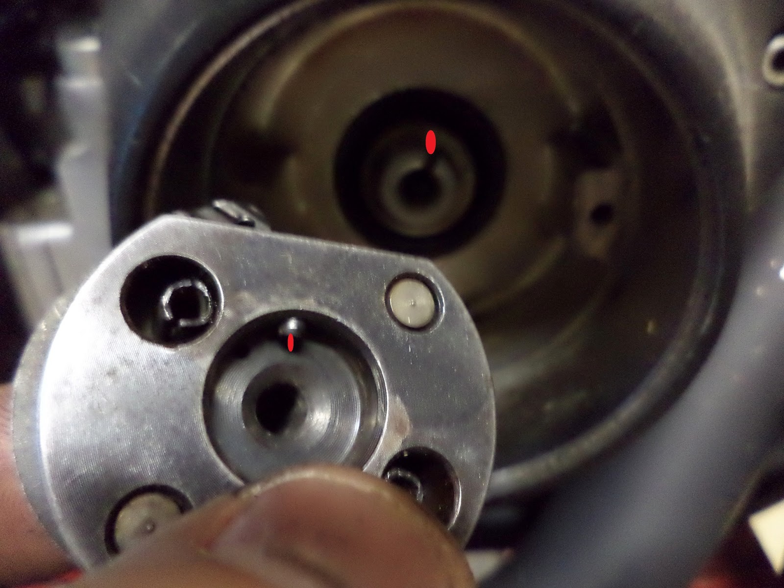
Here's our first set-up to inspect the front wheel bearings. It's the front axle in the wheel with enough other spacers outside the bearings to allow the axle nut to be torqued.

Here's the video of the amount of movement with the front axle spacer. Clearly way too much movement meaning that the spacer was too wide. That's good it's easy to make something shorter.

So we took a quick measurement to know how much should come off to get use into the proper movement range.


The spacer went into the lathe to shave 0.010 inch or something like that I don't recall exactly.


We then restacked everything and torqued down the nut again and here's the range of movement we were looking for. The front wheel is ready to go.


We already knew the back wheel had the opposite issue. The spacer was too narrow, so if you torque that nut properly everything will smash together and lock up.

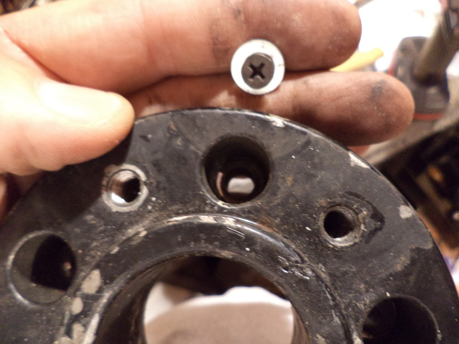
I thought one of these fancy adjustable spacer would to the right. Nope. This spacer has too large of an outer diameter to fit into the mag wheel.

Luckily Columbus had round stock already bored to 3/4 inch ID in his stockpile. So we squared up the end and chamfered the edge of inside and outside diameters.Then check fitted the axle into the round stock and it fit perfectly.


We had an idea of how long the new spacer should be, but we opted to cut it long the first time and finish cut based on its actual fit in the wheel. Columbus marked the cut line with the turning tool first.


DO NOT TRY THIS AT HOME.

Columbus broke his parting tool and hasn't fixed or replaced it yet. So the cut was made with the lathe running and hacksaw. Then the rough cut end got squared up and cleaned up.


We stacked everything to do the check on the new rear wheel spacer. Too wide as exactly as planned.


Then we checked to see how much extra needed to come off.


Back to the final cuts on the lathe.


Now the rear wheel bearing spacer is perfect, too.

Monday, May 27, 2013

Goodbye HI-4, Hello Dyna-S

I decided to dump a somewhat questionable HI-4 fire unit and replace it with a Dyna-S AKA points on steroids.

I bought a dual fire Dyna-S unit and Pat gave me an advance weight set, a dual fire coil, and the special bolt.


I read the Dyna instructions and it stated the magnetic rotor would only fit one way. That seemed wierd because intially it seemed to fit two ways. However on closer inspection I figured out that one way was close, but wrong. The rotor doesn't fully seat.


Proper fitment looks like this and means that the bolt will tighten against the weight set and not magnetic rotor.


Remove the old single fire coil.


Undo all the wires to coil.


Remove the old HI-4 unit.


Undo the wire holder.


Pull the wires all out.


Remove the electronic ignition cup.


I don't think you should have witness marks on the cup like this. This could be part of my problem.


Advance weights have a tang the fits into the groove on the cam. The red spots were added for clarity.


Weights on the cam end.


Magnetic rotor in place.


Rotor bolt in and torqued.


Ignition plate goes in. The pick-up goes at 12 o'clock in a bigtwin. In theory the stand off holes should be in the middle of the adjustment slots and it will be closed to timed.


Route the wires.


Ain't that something. The wires are only long enough to reach the seatpost coil mount location and not the motor mount coil location.


A little solder.


A little shrinkwrap.


That gets us into the neighborhood.


Solder on eyes.


Evidently this is real easy and real easy to screw up.

DO NOT PUT THE BLUE WIRE DIRECTLY TO 12 VOLTS.

I'm told that a lot of Dyna-S units have been destroyed by doing that.


That's about right.


Looking good.


Now to zip tie everything up again. This harness is not too much of a rat's nest.


Tuesday, May 21, 2013

Rough Couple of Days

I watched a tornado Sunday afternoon from kind of close go kind of close to Columbus' house. I watched another one on TV come close to my parent's house. I watched the big one from a power out work cubicle(bunker) on streaming smartphone that came dang close to my house. My family is fine and my house is fine. The power is back on now. I gave blood today. I tired

Friday, May 17, 2013

Simple(too complicated) Shovelhead wiring

I'm in the process of dumping a questionable Hi-4 ignition system in favor of a Dyna-S. When I first built this bike I had drew up my wiring diagram for future reference and troubleshooting. My original wiring had changed so much, with adding things and taking things out that didn't quite work as planned, that my wires didn't look anything like my original drawing anymore. So I redid to match my new lay out.

Yes, it's more complicated that it has to be to run, but I like it. I like fuses for each circuit to isolate things if there's a problem. The RUB-static Kuryakan voltmeter tells me when the regulator comes unplugged. The neutral light should him me until I get my jockey shifting figured out. I drew this up on Microsoft Powerpoint and I like the way it turned out.


Disk rotor spacer fabrication

So I'm still running this goofy 35mm dual disk narrow glide converted to wide glide with an aftermarket triple tree and spacer kit. I would swap it out, but something else always takes my money and the goofiness of it is something to talk about. At any rate Ed and I got to looking at the wheel bearings and spacers and those all need attention. I noticed that all the pads were good except the inboard left pad was metal to metal. It didn't seem to drag last I checked, but I think the rotor needs moved out a bit.

I bought a 0.025 inch sheet of aluminum at the hardware to build spacers out of.

Measure up my holes.


Clamp the metal with a sacrifical board to my drill press table. Then go to work with my circle cutter. Outside diameter first.


Pretty decent. I think slowing the drill speed will help with that hang-up spot.


I also figured out that clamping more like this would help reduce the amount of flex that happened as I cut the sheet metal.


Here are a couple of good starts.


I was at a lose as to how to clamp the circles down to cut out the donut holes. Luckily my cousin Paul was helping and he had the idea to use screws and washers to clamp the circles to board and then clamp the board to the drill press table.


That worked well.


So all that's left to dp are the bolt holes. The true position of the holes is not critical, so I used a screw and washer through one hole to attach it to a board and then used the spacer as a drill guide.


Not real pretty and not perfect, but they should function fine. De-burr the edges for safety sake.


Thursday, May 16, 2013

Common parts Keihin CV40 Harley and CVK Kawasaki Vulcan

I accidentally published this post without any explanation the first time. Sorry.

Contrary to what your average bike night hero will tell you about Harley being all 'merikan. Evo and evo sporty carb's are Keihin and made in Japan. More importantly, contrary to what your average computer jockey partsman at the Kawasaki stealership will tell you, some readily available and cheaper Harley carb parts will work in your Vulcan 1500 carb.

Here's a typical Kawasaki CVK parts diagram for 1500 Vulcan Classic. The numbers are reference numbers not full part numbers.


Here's the list of parts that are common and not common between the Harley CV and the Kawa CV. This is not complete, but it's the ones I know for sure.

COMMON PARTS: Readily available from your local independent Harley shop.
Slow(Pilot) Jets (92064/A)
Top Cap(14025)
Slide Diaphram(16126). Easy to tear up and the Harley part is like $50 and the Kawa is over $100.
Accelerator Pump Diaphram(16014). $10 for Harley one, $40 for a Kawa one.
Accelerator Pump U-ring(92093)
Air Screw, spring, o-ring and washer(16014).
Fuel inlet elbow(shown, but not numbered). If your plastic one breaks get the all brass one from Harley.

ALMOST COMMON PARTS:
Harley main jets will not directly replace Kawa main jets(92036/A~D). However if you replace the Kawa emulsion tube(13280) with a Harley emulsion tube, then you can run any Harley mainjet.

NOT COMMON PARTS:
Float(16031)
Float Bowl O-ring(92055A)


Here's the not common comparison of float bowl O-rings.

Here's the common accelerator pump u-rings side-by-side.