Search

Search all blog posts here.

Search This Blog

Tuesday, March 19, 2013

Shovelhead 4 Speed Saga: Going Up Part 7

I usually give all the pictures and details of everything that goes wrong when I'm building something, but I'm not going to this time. The short story is when we went to torque the kicker shaft nut, which happens to be the part as countershaft nut and pulled the nut's threads. Déjà vu. The kickershaft threads were toast, too. It was actually lucky because somehow we had missed these nasty worn out busted up teeth on the kicker crank gear. Replacing this now will save my knee later.


KevJer donated a good crank gear, I bought a new kickershaft, 16 tooth starter gear, mainshaft kicker tab washer, new kickershaft nut, and key washer. I've put this post together as how-to and not truely a documentary, so some of these pictures still show the old crank gear with the round stop and some show the new gear with the squarish stop and one missing non-critial rivet.

Here's a little bit of the backing up to go over. It's also good to show how to replace the starter gear without a full transmission teardown.

This nut needs to come off. So unbend the tab washer.


An impact got this one of just fine without the need to lock the transmission up.


The starter clutch, key, and starter gear need to come off off the taper. Remember this?
Now go crawl around on the floor until you find the key that flew off with the gears.

I was real curious as to how a 16 tooth and 14 tooth starter gear could both mate up to same crank gear. They both work fine, but the 16 tooth is suppose to easier to kick. We shall see.


Starter gear goes here.


Key goes here. Remember there's an up and down to it for it to fit.


Starter Clutch gear, tab washer, and nut go on. How we going to lock up the transmission to torque the nut when the lid is already installed?
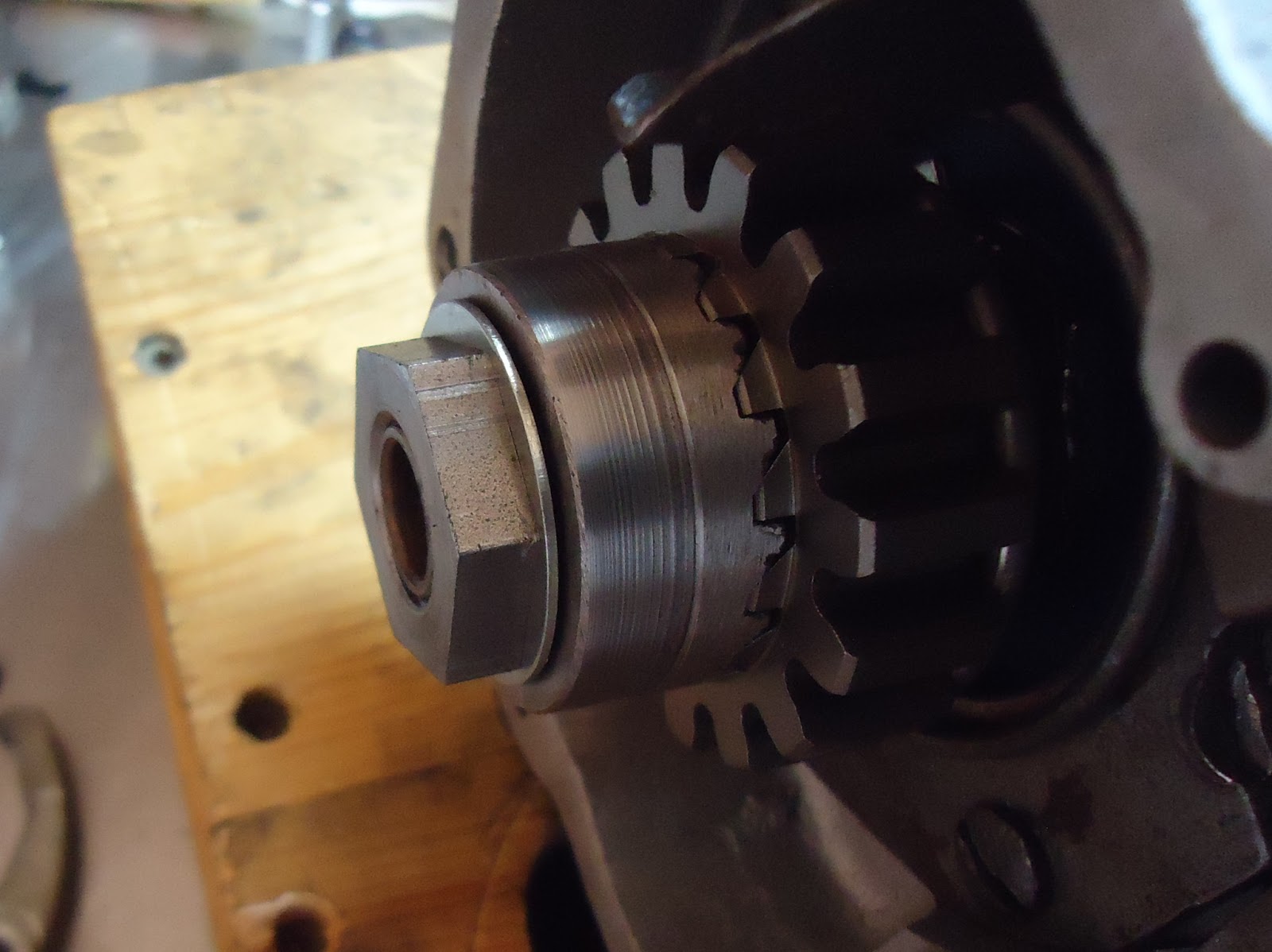

If you put the transmission in first and plastic primary chain wedge nicely right here.
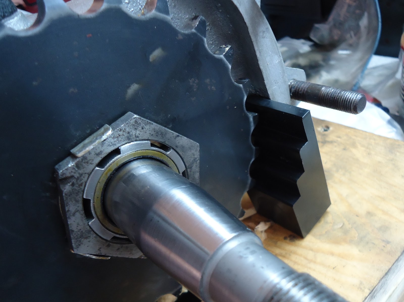

Torquing the nut is not a problem.
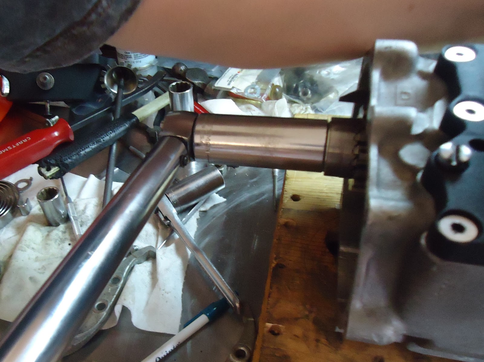

Bend the tabwasher.


Re-install the pushrod assembly.


Kicker cover and pieces all laid out.


This has most of the parts shown, but I wasn't able to get any diagrams with the clutch release related hardware. Given the mod's to this cover with the bushings and seals already in place I omitted those from this diagrams as well.


Fill plug(1) threads into the cover(2).


The clutch release parts laid out. (L to R) Clutch release finger stud, clutch fingers, thrust washers, and e-clip. This set-up goes with the heavy duty aftermarket cover. So I don't know it if it stacks exactly the same as a stocker, but it should be close.


Stud goes through the cover, the finger, thrust washer, another boss in the cover, and thrust washer.


E-clip goes here to hold it all together.


Kicker spring stop(4) goes here.
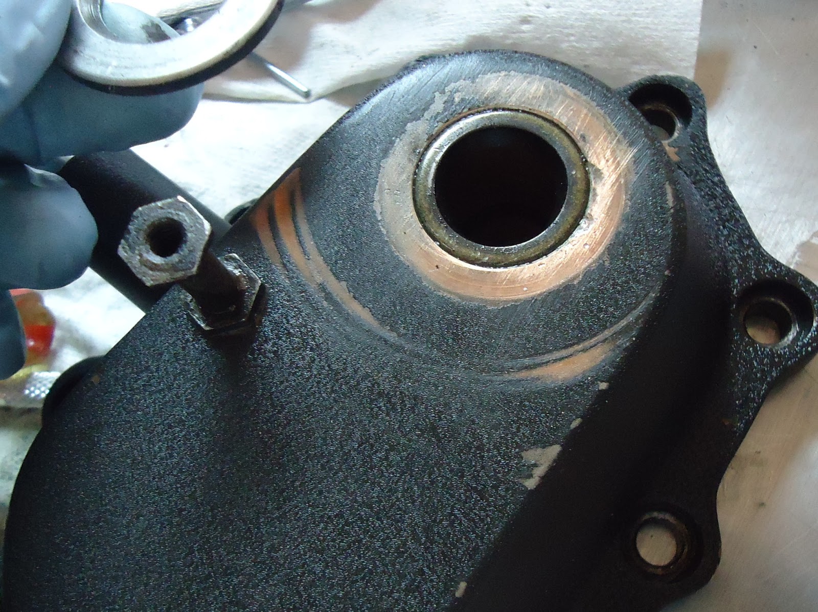

Kicker shaft thrust washer(5) goes here.


Oil up the kicker shaft(7) and install it.


Work the spring(6) on.


Roll the spring and shaft until the spring end finds the stop.


Install the crank gear. With the spring hook touching it's stop on the outside, the crank gear stop should be foward and up from the straight down(when installed on bike) position in the cover.


Tabwasher(9).


Nut(10).


Hold the flats of the kicker shaft outside the cover and torque the nut.


Bend the tab washer.


Why not bend two.


We're not quite ready to install the cover, but this is a good time to show how the stops and springs would together so your kicker will return to straight up and down after you kick it.

The crank gear stop is marked with the arrow on the left and place it should rest is marked with the arrow on the right.


To make this work, get a wrench on the flats of the shaft.


Rotate the shaft so the stop of the gear finds it's resting spot in the case. You should be working against the spring and this point. This is the tension that will put your kicker arm back up straight every time. I'll do a video of this when I do my final install.


Meanwhile this is when I discover that this hole seriously needs a heli-coil repair. That would have been easier to fix on a bare case before I build the transmission. Getting closer, but it's always something.


Monday, March 11, 2013

CT70 Front Wheel and Tire Build


These Trail 70 wheel are another unique piece of motorcycle parts. The split rims and seperate hubs are something I haven't played with before and something you can screw up easy enough. There are no front and rear rims, but there are front and rear hubs and definately a right and left to everything.

The right rim is the place to start. A right rim has the hole for the valve stem and the have a deeper offset.

Lay the right rim down on the bench and put the left half on it.


The front hub sets on the left side with the brake and nut holders out like this. This was just for planning sake because the tube and tire have to go on before the wheel goes together.


Pop the right half into the tire.


Find the hole for the valve stem(tip of middle finger). Put the stem through the hole. Bend stems aren't stock, but cheaper and functional.


Work the tube into the tire.


Flip the wheel to make sure this looks good.


Flip again and align the holes(big with big and little with little) of the left rim with the holes on the right rim and push the left rim into the tire. DO NOT push the left rim into the tire and expect the rim and expect to be able to slide the rim into alignment. Trust me.


Here's the wheel hardware. Four little sets and four bigger sets.


The little ones hold the wheel together. Coming from the right side; bolt, flat washer, lock washer, and nut.


Ensure the you haven't pinched the tube between and snug the hardware


The big sets hold the rims and the hub together. The hub lays on the left side of the rims and the nut goes into the hub. The bolt and lockwasher come in from the right side.


Flip the wheel and tighten the bolts.


I couldn't find a torque spec so I smoked everything down with only a quarter inch ratchet. Hopefully that's tight enough, and I can't break anything with the little ratchet


Now to the rest of the front hub and our old friend the speedo gear.
Amazingly I haven't lost this tiny screw. I need to check the threads for it after the powdercoat though.


Fits fine.


Grease the gear.


Into the housing.


This piece is a tightish fit and you need to align the set screw notch with the hole from the start for sure.


It needs just a little squeeze and it's tough to get a good push on.


Hole and notch aligned.


Set screw in.


Grease everything and put the big gear in.


The powdercoat on the inside made this a bit tight.


The stand offs from the gear fit into these slots in the hub.


Temp install the plate and whack it to fully seat the gear.


Take it back apart and the seal here.


This screw and sealing washer go here. I'm not sure what this does, but I think it's a grease port. Yeah that screw is ugly when everything else looks nice.


Brake cam.


Grease and install it.


Wrestle the new brake shoes on and try not to get grease on them.


Use brake cleaner to clean all the greasy fingerprints you got on the brake shoes.


Well this was an oops. The dot on the cam should line up with the dot on the lever. So the cam is 180 degrees out, but it should work just fine, because I don't want to reinstall the shoes again.


Still lined up, just not together.


Bolt, washer, and funny nut go like this.


Good stopping point. I still need to halfway inflate the tube to get it set. Then full inflate it and whack the tire until the bead is set. And there's a bearing seals the needs to be installed on the right end of the hub. Otherwise the front wheel is good to go.