2. Topend Teardown and Inspection
3. Head Teardown
4. Valve Lapping
5. Valve Installation
6. Hydraulic Lash Adjusters(HLA)
7. Cylinder and Piston Installation
8. Head/Cams/Rockerbox Installation
9. Clutch side Buildup
10. Alternator side Buildup
11. Putting the Engine in the frame
Getting the engine out of the frame
That's my friend "Hot Sauce" with a quick cup of inspiration.

Tank and seat gone. Hot Sauce goes too fast to get step-by-step action shots.

Put this these parts off to side.

Drain the anti-freeze.

Left floorboard off.

Right floorboard off.

Hot Sauce unplugging the electronics and he's already got the left side chrome dust cover off.

Drain the oil.

Jackstands under the rear axle.

Right subframe piece comes off.

Motorcycle jack goes under the engine. Engine mount bolts come out and now on to disconnect the driveshaft.

A big pry bar to move the jack sideways and the engine forward a bit.

Engine is officially disconnected. Use a pick in the hole to push the keeper out.

Here's a better look at the keeper.

This is the spring and keeper. Bag those and don't loose them.

Roll the engine out on the motorcycle jack, just under 2 hours. Leaving a big hole.

On to the work cart. I don't have any engine stand just some boards to keep things level.


Topend Teardown and Inspection
Lots of little bolts hold the rocker box covers.

Rear head. It was the noisy one, but nothing is obviously wrong.

Front head looks okay at initial inspection.

Rear oil line off.

Take off the headnuts and bolts. An impact wrench is highly recommended.


Just like whack-a-mole.

Underside of the rear rocker box. Easy to get an idea if any of the hydraulic lifters are soft.

Rear cam exposed.

Here's the rear compression release(KACR). I won't be putting those back in.

On to the front cylinder. Remove the front oil line.

Front headnuts and bolts off.

Whack-a-mole didn't get this one done. There are two little pry spots. There are two notches on both rocker boxes.


Front cam.

Underside of the front rocker box. These hydraulic lifters seems good.

Behind the leftside dustcover is the outer alternator cover. You can remove the two slotted plugs and turn the motor with the nut in the middle and observe the timing marks in the small hole, if you're not needing to go all the way into a motor.

Here's the alternator rotor remember it's a big magnet and it has all the timing marks.

The front shift shaft goes through the alternator cover.

Finally found the timing mark on the crank case. It didn't look exactly like the book picture.This picture is not completely accurate either. The mark cast into the crankcase is for timing, but there are two set so marks on the rotor. The set on the face is observable through the inside hole at 3 o'clock and the marks on the circumferential face of the rotor line up with the crankcase timing marks at 11 o'clock.

Taking the camchain tensioner off.


Got both the tensioners off and the cams out, but didn't a picture of the cams coming out.
The spark plug tubes have to come out to get the heads off. It takes 27mm external hex. So I took a 27mm wrench with me to hardware store to check the nut size and bought a bolt and two nuts to fit.

It works.

The camchains were rubbing before I did those camchain tensioner extenders.
Both tubes.


Two cap nuts hold each head to the cylinder. They are tight and hard to get at.


Front head off and it looks like this.

Top of the front piston looks like this.

Rear head coming off.


Rear head off and it looks like this.

Top of the rear piston looks like this.

Both headgasket surfaces seamed wet with antifreeze and both head came off without much any effort at all. I wonder if the head gaskets were leaking causing the oil usage and/or the radiator boilover.
Front camchain tensioner shoe.

Rear camchain extensioner shoe.

Two nuts hold each cylinder on.

Front cylinder off and piston hanging out.

Front cylinder on the table.

Rear cylinder coming off.


Rear cylinder on the table.

Both cylinders went to the machine shop with the oversize pistons and rings.
Both pisons hanging out of the crankcase.

Here's what a leaky intake valve seal looks like.

Here's what a really bad cam follower looks like.

Here's the matching spot on the cam.

Look at the rest of this cam and it's smoked.

Left side inner alternator cover off onto the bench.

That's the alternator rotor. We couldn't get the penny-on-a-string to lock up the motor on this side so we had to use the penny on the clutch side.

The inner alternator stator.

Take it off.

There's the front cam chain.

The guide is bent I'm not sure if that was already that way or if I did it turning the motor backwards at some point working on it.

Here's the bent camchain guide.

There is a book spec for camchain stretch, but it's safe to say that a chain shouldn't bend sideways this much. We are going to need new camchains.

On to the rightside and rear camchain.I missed taking of pictures of taking off the right side cover.
The it's simple, but keep track of the bolts. I use a the cardboard from the new gasket with the gasket outlined on it, but here's cheat sheet if you need it.


You actually don't have to take this bolt off to get the starter gear off.

The waterpump chain and tensioners have to come off.

Waterpump chain and gears.

Lock the motor with a penny again to get this bolt.

I didn't get any pictures of taking the clutch basket off, so look here for more info on that.
A little fuzzy, but there's the rear camchain.

Head Teardown and Inspection
The cam and follower were more expensive than used heads. So these are the used heads I'm going to go through.

Early heads, no carb warmer connection.

I'll rob this one off the my first heads so I won't need a different hose.

Into the "new" front head

so far so good...

This cam is good.

Now to get the valves out. This my cheap eBay special valve spring compressor.

Get it done!

Compress the spring until you can get the keeper out and slowly decompress the spring.

Front right exhaust valves, springs, and keepers.

Front right exhaust valve seat and guide.

Bag and tag everything. All the pieces need to go back where they came from. I did this for every valve, but this will be the only picture for reference.

Front left exhaust valves, springs, and keepers.

Front left exhaust valve seat and guide.

Front right intake valves, springs, and keepers.

Front right intake valve seat and guide.

Front left intake valves, springs, and keepers.

Front left intake valve seat and guide.

Front head tore down.(Old seals still on.)

Into the rear head.


Cam is good, picture is fuzzy

Followers good.

Rear right exhaust valves, springs, and keepers.

Rear right exhaust valve seat and guide.

Rear left exhaust valves, springs, and keepers.

Rear left exhaust valve seat and guide.

Rear right intake valves, springs, and keepers.

Rear right intake valve seat and guide.

Rear left intake valves, springs, and keepers.

Rear left intake valve seat and guide.

Rear bare head.(Old seals still on.)

Valve Lapping
Here's the before on the front cylinder.

Here are the valve seals. They have to go.

Pry 'em off and throw them away.

Get the lapping compound.

Put a light coat on the valve sealing area.

Put the valve in to the hole it came out of and twist it back and forth, back and forth.

When you clean off the compound and see a nice even gray line in the seat, you're good to go.

You need a nice line on the valve, too.

Repeat that three more times and the front is done, but be sure to wash everything to get the compound off before you build the motor.

Repeat that 4 more times and the rear is done, too.

Valve Installation
Time to wash the lapping compound of the heads.

Rinse the heads.

This was something I hadn't noticed yet. The rear head has a basketweave in the casting...

The front head is smooth.

Blow dry the heads to get the water out of the crevices.

Wash lapping compound of the valves, too. Don't put those back in the bag wet or things will get ugly.

Now let's put the valves back in. Oil it up.

Put it in the head.

Oil the seal.

Push the seal on.

Put the springs and retainer on with the tool.

Get the split keepers ready.

Work those in.

Take the tool off and one valve is done.

Do that three more times and the rear valves are done.

Now do it for the front, and the valves are all done.

Hydraulic Lash Adjusters(HLA)
Just pull them out with pliers.

Here's the checkball to burp. I used a tiny L-key to push it in, but the cut off thumb tack from the manual may be a better idea, because you won't push too far and hurt the spring.

Now clean them with WD-40.

Burp and pump up, a couple of times to flush out the junk.

Now that they're clean, we will fill them with fresh oil. Squeeze the adjuster and open the ball. Don't release it yet.

Now release the ball with HLA submerged in new oil. Purge, clean, and refill all eight of them.

Now check the tiny hole in the rockers. Make sure they all are clean.

Here we are washing again.

Blow dry.

Oil the steel parts so they don't rust. A periodic correct oil can is the only way to do this.

Put the adjusters into the rockers.


Okay enough with the heads for now. What's with the ATF?

I was told by Hotsauce via The Judge that you can marinate the paper gaskets in ATF and they will stay where you put them during assembly and if you have to take things apart the gaskets won't stick and you can re-use them. Looks like a horror movie though.

Let's get this motor back together.
Cylinder and Piston Installation
We had to replace the pistons with the oversized pistons. The cylinders were machined to match the pistons. The cylinders are back from the machine shop and they need washed, too.

Do you see the different surface finish? These were still a touch out of round even after the oversize. You can see, but not feel it. It is under where the rings will run so hopefully everything will be okay.

After washing the cylinders, all of the steel parts need to be oiled to keep them from rusting until I get the motor together.


Old pistons have to removed.
Take out both wristpin snap rings and throw them away.


Gently tap out the wristpins. The screwdriver's handle made a nice soft drift.

Out it comes.

Old piston is gone.

Repeat thosee steps for the other piston.

The pistons have a directional arrow so you want to the first one snap ring into the groove the will be on the camchain side of the cylinder. This will make second snap ring easier to install without working around the extra studs in the case.

Slide the ring so that the gap in the ring is opposite the gap in the piston.

Oil the piston where the wristpin rides.

Oil the wristpin and the connecting rod hole.

Line everything up and put the wristpin through the piston and connecting rod.

Install the other snap ring.

Again move the gap of the ring opposite the gap in the piston.

Piston is on.

Get ready to do the piston rings. READ THE BOOK! It is easy to put the piston rings in upside down, backwards, gaps misaligned or otherwise wrong.

Work the rings into the grooves.

Ringed and ready.

Oil the rings and the pistons.

Old Easyrider trick, use a hose clamp as ring compressor.


Oil the cylinder wall.

Slide it on.

Take the hose clamp off, when the rings are inside the cylinder.

Looking good.

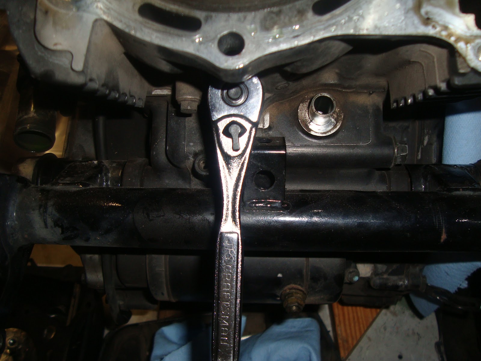
I looked up the torque value on these two nuts. 18 ft*lb. I then realized I could fit a torque wrench on it. I used my calibrated elbow instead. (Add metric torque adapters to my Christmas list.)

The next picture should both be cylinders on with pistons in them, but we fought the rear oil rings for 2 hours maybe. The wavy oil ring would not go in. It acted like it was too big or something. Here it is laughing at us.

Plan B. Put the piston into the cylinder on the bench then attach the piston to the connecting rod. Take out one snap ring and the wristpen. We used a 14mm socket and extension as drift this time to clear the installed snap ring.

Work the piston and rings into the cylinder on the bench with the wristpin hanging out.


Now put the cylinder, piston, rings, and wristpen onto connecting rod.

Tap the wristpen through and put the other snapring in.

Now we have both pistons and both cylinders installed.

Head/Cams/Rockerbox Installation
New camchains.

Start fishing.

Through the cylinder.

Put the guide back on.

Now the rear one.

This gear can go on.

Headgasket on.

Make sure the plastic camchain shoes are hanging out of the jug BEFORE you put the heads on.


Put the head on and fish the chain.

Chain over the cam gear.

Okay time to time the chain to the crank. The books were a little goofy. The picture showed the lines on the gear even with head where you could read "F", but the book stated lopes up. The book pictures of the rotor marks and the case marks didn't match the book either. The lettered marks were where you could see them with the sidecover on. After playing with the crank. We found lopes down and the proper rotor marks for the case mark.

Lube the journals.

There is no gasket between rocker box and head because they are machined as set. Guy Mobley at http://www.shermscycleproducts.com/ recommended permatex 29132 to seal the rocker box top and the cam plug.

Smear it on with a thin coat and let it get tacky.


Put it together.

Torque time, follow the book sequence.

Looking good.

Looking good.

Put the camchain tensioner in. That's the wart halfway down the front cylinder.

Here's the instructions on how to properly time the cams. It's easy to screw up.

Here's the motor with the cams in and the rocker boxes on.

Rear tensioner going in.

Replaced the water line o-ring and installed the water line on both heads.

Ready for the top. I used the permatex to glue the rubbers in the cover.

Line it up, so you don't mess up the gasket.

There is a torque wrench attached to this speed handle.

Forget to put the oil line on 'til now. Still doable, but would have been easier before the top went on.

Put the spark plug tube back in.

Both covers on.

Starting to looks like a motor again.

Clutchside Buildup
Ready to go up with clutch side.

Water pump gears and chain, etc.

This shaft has two pins and two snap rings to hold it in place

Put the shaft into the bearing the case and the pin the slot of the gear. Don't put the other gear on crankshaft yet. (Like I did in this pic.) Also roll the gear so that the pin is horizontal so if won't fall out.

The primary gear goes tall shoulder toward the inside, before the waterpump gears.

Both of the waterpump gears and chain slide on together.


Three dowels and three bolts hold the tensioner piece on.

The tensioner is on. The spring is kind of wierd because it's not really captured, just hooked on the threads of a bolt. The starter gear slides back onto its place with the one way clutch.

Clutch basket on the splines.

Washer on the shaft.

Inside of the clutch basket goes on.

Stack the clutch.

Steels and frictions, steel and frictions.

The last friction plate is offset into the stand off.

The clutch spring stack up. I am using a meanstreak clutch spring and Judge's clutch washers.
Click here for details.


The end of the basket goes on.

The spring stack goes on.

The nut goes on.

The penny with ribbon locks the motor gears.

Torque the clutch hub nut to 110 ft*lb.

Switch the penny position and torque the primary nut to 110 ft*lb.

Clutch rod and throwout bearing go in.

The cap and thrust washer go on. I didn't get a shot of the washer in the cap, but it's there.

The snap ring holds the cap in place. This side is done. I can't put the cover on yet, because I still need to lock the gears with a penny to torque bolts on the other side.

Alternator side buildup
The alternator side was a little tricky. The Clymer repair manual says up to 2004, but they do not cover the dual stator set-up that came out like 1999 or so. The early models had the primary gear attached to the rotor and the counter balancer mark was on it.
The left side primary gear is separate from the rotor on the dual stator set-up.

It only fits on the shaft one way.

You need to turn the motor counter clockwise to align the mark on the primary gear with mark on the counterbalancer gear. Like this.

First stator goes on.


Rotor goes on.


Lock the motor and torque this bolt. I forget the value. I think it's 58 ft*lb.

This cover is next. This gasket is easy to confuse up from down and magnet in the rotor wants to grab it.


This plugs need to go on top of the gasket and Moto-Seal goes on it.

Slide the cover on and bolt it up. These bolts get torqued to 88 in*lb.


Next comes the shift shaft. Grease the end that goes in the crankcase.


Put the splines of shift lever over the other shaft and put that bolt in.

Another gasket for the outer alternator cover.

Grease the shaft of the shift shaft and slide the last cover on.


Torque those to 88 in*lb.

The bolts in the right side are different lengths in different spots.
Cover on.

Bolts torqued to 88 in*lb.

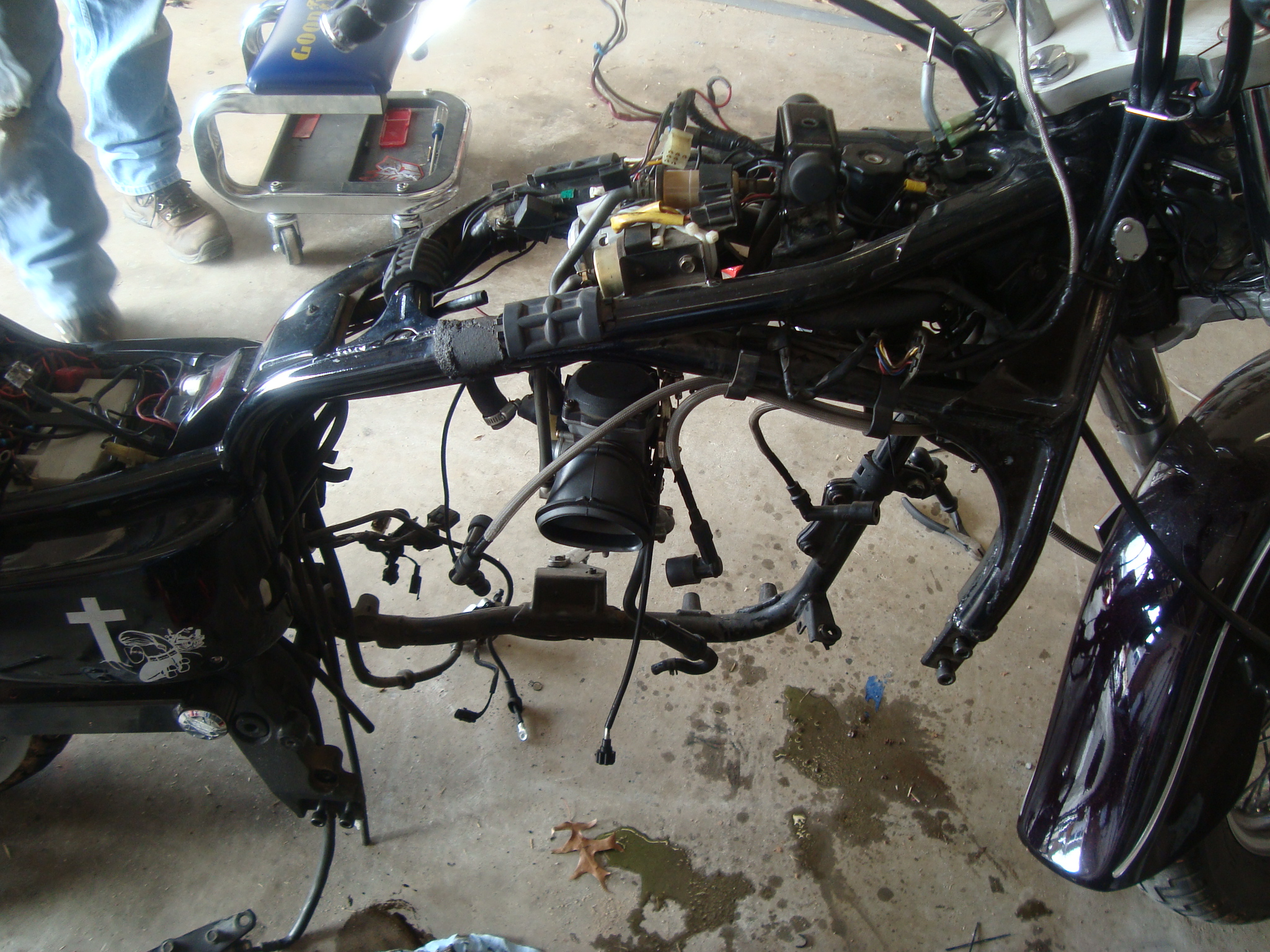
Putting the engine into the frame
Engine into the frame
New boot on the output shaft, because the old was nasty.

New intake o-rings.

Intake going on .

Now I just need to get the engine from the cart to the jack to the frame. I'll have to have some help.

Les and Pat came and now we can get to work. First we spin the rear wheel ...

to get the hole in the drive shaft where can see it. More on this later.

Grunt!

Drop! I mean sit down on the motorcycle jack.

Line it up with frame.


This spring and pin keep the output shaft connected to the driveshaft.
The spring goes inside the output shaft the pin goes in the hole. This lines up with hole in the driveshaft.
Like this.

Once you get the shaft connected, start with the motor mounts and make sure the clutch line is routed properly.


Now the radiator and the subframe piece.

Looking good,

The floorboard and brake go on.

Mount the rectifiers.

Here's the piston for the slave cylinder

New seal.

Put everything back together and bleed the clutch line.

Mighty vac!

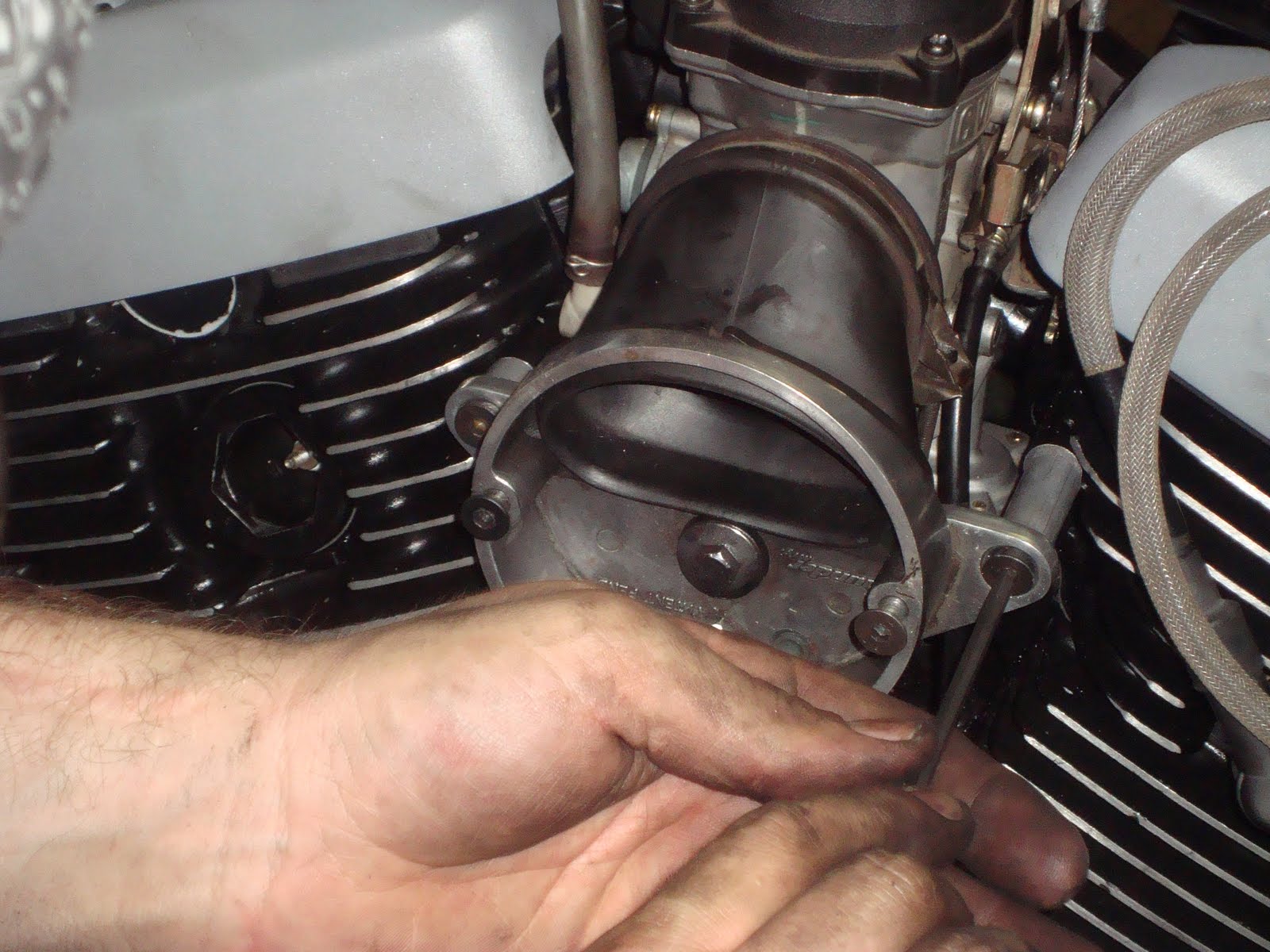
Now to the carb.

Connect the plate and the cables.

Gas inlet.(that's important.) The choke cable goes over the top of the rear jug.

Carb in the boot.

Breather coming together.

Cover on.

Now for the pipes.


What's this green stuff? Antifreeze? You mean like in a car?

New oil filter. (It helps to use the right one, because my mini-van oil filters are about the same size, but they don't fit no matter how hard you try.)

Don't forget to put oil in it.

Yea! I get to use my new I.V. gas tank.


Hook up the dash.

LIGHT IT OFF!
The battery is a touch weak so we charged for a bit and tried again.Runs better than new. Get it warm and burp the coolant.
Finish it up.
Left side cover.

Toe shifter.

Heel shifter.

Floorboard.

Dash and Tank. Empty the IV bottle, too.

Ready for a test drive. Pat and Hotsauce laughed at me because I didn't a jacket, too.

