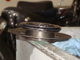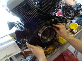
Fresh headgaskets. Now we can get to work.

The boys came out to the garage to help, too.
Again make sure there is plastic part hanging of the jug BEFORE you put the heads on.


Fast foward. (If you need to see this part, click here)

Heads are on again.

Replaced the water line o-ring on both heads.

Ready to go up with clutch side.

Water pump gears and chain, etc.

This shaft has two pins and two snap rings to hold it in place.

Put the shaft into the bearing the case and the pin the slot of the gear. Don't put the other gear on crankshaft yet. (Like I did in this pic.) Also roll the gear so that the pin is horizontal so if won't fall out.

The primary gear goes tall shoulder toward the inside, before the waterpump gears.

Both of the waterpump gears and chain slide on together.

Note: No dowel in the above picture and two below. I robbed one from the side cover. I don't know what happened to it, but I blame the last guy that rebuilt it.

Ready to go. I had to rob a dowel pin from the left cover because one of the waterpump chain tension dowels was missing, I'm blaming the guy who rebuilt it.


The tensioner is on. The spring is kind of wierd because it's not really captured, just hooked on the threads of a bolt. The starter gear slides back onto its place with the one way clutch.

Clutch basket on the splines.

Washer on the shaft.

Inside of the clutch basket goes on.
Stack the clutch.


Steels and frictions, steel and frictions.

The last friction plate is offset into the stand off.
The clutch spring stack up. I am using a meanstreak clutch spring and Judge's clutch washers.
Click here for details.


The end of the basket goes on.

The spring stack goes on.

The nut goes on.

The penny locks the motor gears.

Torque the clutch hub nut to 110 ft*lb.

Switch the penny position and torque the primary nut to 110 ft*lb.

Clutch rod and throwout bearing go in.

The cap and thrust washer go on. I didn't get a shot of the washer in the cap, but it's there.

The snap ring holds the cap in place. This side is done. I can't put the cover on yet, because I am short a dowel AND I still need to lock the gears with a penny to torque bolts on the other side.
The alternator side was a little tricky. The repair manual says up to 2004, but they do not cover the dual stator set-up that came out like 2000 or so. The early models had the primary gear attached to the rotor and the counter balancer mark was on it. To be transparent, we put this together wrong once and redid it. I am going to show only the right way on this blog entry.
The left side primary gear is seperate for the rotor on the dual stator set-up.

It only fits one way.

You need to turn the motor counter clockwise to align the mark on the primary gear with mark on the counterbalancer gear.

Like that.

First stator goes on.

Rotor goes on.


Lock the motor and torque this bolt. I forget the value. I think 58 ft*lb.
This cover is next.

This gasket is easy to confuse up from down and magnet in the rotor wants to grab it.


This plugs need to go on top of the gasket and Moto-Seal goes on it.

Slide the cover on and bolt it up.


Those bolts get torqued to 88 in*lb.
Next comes the shift shaft. Grease the end that goes in the crankcase.


Put the splines of shift lever over the other shaft and put that bolt in.

'nuther gasket

Grease the shaft of the shift shaft and slide the last cover on.


Torque those to 88 in*lb.

We'll call that a day.

I did have to lay this cover on it just for inspiration I can't put this cover on the motor until it is back it the frame.

No comments:
Post a Comment