Search

Search all blog posts here.

Search This Blog

Saturday, October 16, 2010

Almost wired

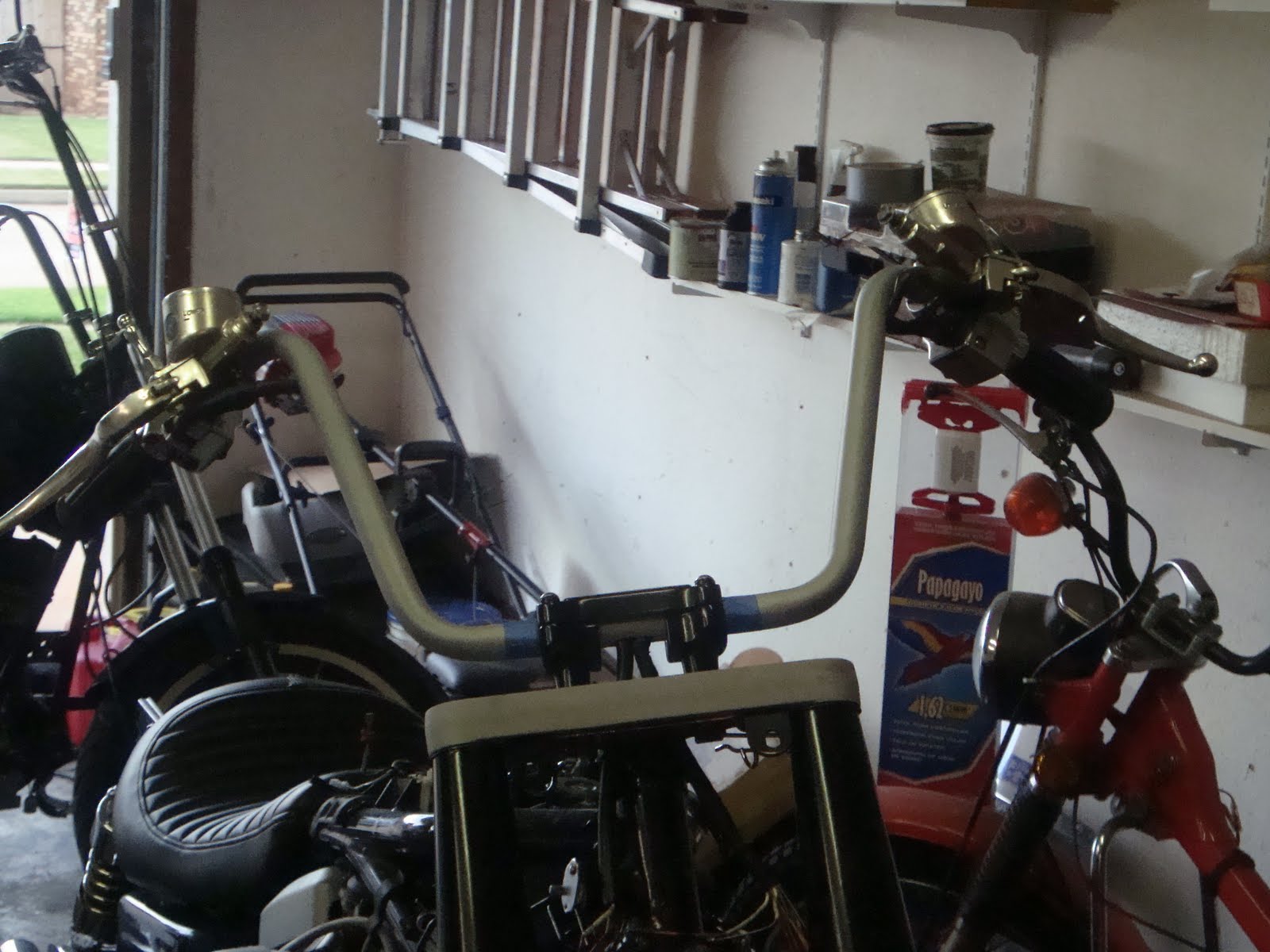
Okay here's the bar on the bike for mock up. I thought the chrome would look good on the light trim bezels, but those are getting the aluminum powdercoat after I get it all figured out and get another paycheck.


The wires for the marker lights are of course too short and the bullet connectors are too big.


So I got these from Radio Shack and they should to the trick.


They need cleaned up a bit.


This is a bit tedious, but I only need to do it six times.

More rosin and solder.


After a fit check, I think they need to be shorter to fit inside the shrink wrap on the stock connectors. No problem.

All done.


Heat shrink for the spot light wires.


A new wire to feed the spotlight switch.


I'm using push mount wire ties on the lightbar. Anybody need some of these? I really can only use two, but I had to buy like 200.


But they work like they should. Leave those loose for now.


More shrinkwrap.


Nice and tidy. I wanted to hide the wires in the spotlight bar, but that was not going to happen given the size of the tube.


Next we have these wire ties.


They will mount to the bolts sticking out here. I had to get longer bolts. Put on the regular nuts, then the wire ties and then another nylon lock nut.

Oops, I need more shrinkwrap.

One ground wire is too short, too. So I'll piggy back it to another ground wire.


With the wires back in the headlight it's time to get to business. I'm putting a ground junction on bolt and nut in the bucket. This is the hardwired ground to connect the rest of the ground to, because I doubt a body ground will work with all the powdercoat.


Marker light connections.


New connection from the headlight "on" wire to the switch for the spotslights.


I like these connectors with a double spade terminal.


Marker lights seem to work.... but the left one is giving me problems and acting sporactic.


Ground was loose. I don't think you are supposed to take these apart so many times.


Easy enough fix. Rosin the wire and resolder, no extra solder needed.(I'm using the clip as heat sink so the grommet and wrap don't get too hot.)


I put it back together and still had problems and messed with it some more and started popping fuses. Yep, shorted one contact wire and almost broke off the contact tip. I couldn't find any contact tip pieces so I bought a new pigtail. Of course both contacts will need to be replaced, because the holes in the bases are different.

No pictures of how I did it, because it took two hands and my wife's two hands to make it work. I cut the contact with a tiny bit of wire off the pig tail. Stripped the wire and applied rosin. Then I presoldered that wire. I rosined the wire on the bike and then held the presoldered wire next to the bike wire and heated it until solder flowed between them and then I moved the iron. Amazingly that seemed to work.


That's alot of bare wire so I shrink wrapped them, but that was too fat for the base go back over. So I had to cut the wrap off. So I figured I would try liquid electrical tape. I can't remember what I bought this for, but it was still new in the package in my tool box.


Looks good and if this fix actually works, I will be impressed with myself. It calls for 4 hours to dry, seems conservative, but I'm tired of this nonsense today.

Sunday, October 10, 2010

Wiring the bars

Time to wire these bars. Start with the right side because it's simpler. Here's the wiring diagram. the only thing that could be a problem is two black wires, but they just connect at the brake switch, so swapping those won't be a problem.


Draw a plug map. I thought I could get around depinning, but I really can't.


Use a pick to push the tab down and slide out the tab.


A little bit of messing and you have the plug off.


I checked to see if the stock wrap will fit in the hole.


It fits so I want to leave enough to protect the wires in the hole.


Carefully cut the wrap, so you don't have to solder where you hadn't planned.


Ideally I would use the correct colors for the extensions, I didn't have nearly colors in my stash and I did have roll of white in the correct gage so. I that's I used. I cut 8" sections to use.


Pick a point to cut. (Remember to put the next cut about an inch from the last one, so the solder joints don't make a big wad.)

Strip the wires.


Rosin the wires.


Solder the wires in both places. Give the tug check.

Shink wrap.

Do that like five times and the right side is ready to be routed.


What's with the earplug and electrical tape?


Tape the plug string to your wires and put the plug in the hole.


Blow the plug to the other hole.


Pull the plug and push the wires.


Not ultra clean and sexy, but pretty good.


The left side is worse. 11 wires to go through, and actually 13 wires to start with at the housing. Three ground wires(Black with yellow) junction together inside the harness.

It's pretty much the same steps, but if I had a do over I would get rid of the factory wrap. It's too big and bulky when it's full of wires. There are three wires from clutch switch one goes to that ground junction, and other two go to the little plug. I would definately break the ground junction and shrink wrap the big bundle of wire together and the little bundle together, then resolder that junction. The tight shrink wrap would have fit into the hole a lot better.

Here the end results of my work, again not super sexy, but acceptable for this build.


Time to fix this. I think I put these rubbers on wrong. The big one goes on the bottom.


Yes, much better.


Top tree off the bike and routing the wires.


Windshield bracket, hose guide(that may get worked over yet), bottom clamps, and clamp bolts go on.


Top clamp on.


Bars, controls, and top tree back on the bike.

Pretty clean. It's a shame that I have to add a brake line, clutch line, and throttle cables.


This looks okay.


Fits good with the new seat.


All I need to do now is finish it.

Speedo cable guide

Well, we had some paint issues and never got a chance to repaint the front fender and then I wasn't able to run a tranny speedo so I ran a front wheel speedo. At any rate it's about time to repaint the fender so better cable guide will be needed. You can see that it rubbed the fender a bit.


I found this guide at the bike salvage yard, I think it's a Yamaha part.


Mark it.


Drill it.


Install.

Dissconnect the speedo cable.

Unscrew this end.

Install the fender.


Reconnect the speedo cable.


Cable looks good, but the brake line is tweaked from being tied to the cable so long.


Barely loosen the brake line on both ends.


Perfect.