Search

Search all blog posts here.

Search This Blog

Monday, March 11, 2013

CT70 Front Wheel and Tire Build


These Trail 70 wheel are another unique piece of motorcycle parts. The split rims and seperate hubs are something I haven't played with before and something you can screw up easy enough. There are no front and rear rims, but there are front and rear hubs and definately a right and left to everything.

The right rim is the place to start. A right rim has the hole for the valve stem and the have a deeper offset.

Lay the right rim down on the bench and put the left half on it.


The front hub sets on the left side with the brake and nut holders out like this. This was just for planning sake because the tube and tire have to go on before the wheel goes together.


Pop the right half into the tire.


Find the hole for the valve stem(tip of middle finger). Put the stem through the hole. Bend stems aren't stock, but cheaper and functional.


Work the tube into the tire.


Flip the wheel to make sure this looks good.


Flip again and align the holes(big with big and little with little) of the left rim with the holes on the right rim and push the left rim into the tire. DO NOT push the left rim into the tire and expect the rim and expect to be able to slide the rim into alignment. Trust me.


Here's the wheel hardware. Four little sets and four bigger sets.


The little ones hold the wheel together. Coming from the right side; bolt, flat washer, lock washer, and nut.


Ensure the you haven't pinched the tube between and snug the hardware


The big sets hold the rims and the hub together. The hub lays on the left side of the rims and the nut goes into the hub. The bolt and lockwasher come in from the right side.


Flip the wheel and tighten the bolts.


I couldn't find a torque spec so I smoked everything down with only a quarter inch ratchet. Hopefully that's tight enough, and I can't break anything with the little ratchet


Now to the rest of the front hub and our old friend the speedo gear.
Amazingly I haven't lost this tiny screw. I need to check the threads for it after the powdercoat though.


Fits fine.


Grease the gear.


Into the housing.


This piece is a tightish fit and you need to align the set screw notch with the hole from the start for sure.


It needs just a little squeeze and it's tough to get a good push on.


Hole and notch aligned.


Set screw in.


Grease everything and put the big gear in.


The powdercoat on the inside made this a bit tight.


The stand offs from the gear fit into these slots in the hub.


Temp install the plate and whack it to fully seat the gear.


Take it back apart and the seal here.


This screw and sealing washer go here. I'm not sure what this does, but I think it's a grease port. Yeah that screw is ugly when everything else looks nice.


Brake cam.


Grease and install it.


Wrestle the new brake shoes on and try not to get grease on them.


Use brake cleaner to clean all the greasy fingerprints you got on the brake shoes.


Well this was an oops. The dot on the cam should line up with the dot on the lever. So the cam is 180 degrees out, but it should work just fine, because I don't want to reinstall the shoes again.


Still lined up, just not together.


Bolt, washer, and funny nut go like this.


Good stopping point. I still need to halfway inflate the tube to get it set. Then full inflate it and whack the tire until the bead is set. And there's a bearing seals the needs to be installed on the right end of the hub. Otherwise the front wheel is good to go.


Tuesday, March 5, 2013

CT70 Bike Build Stand

These Trail 70's are interesting bikes. I was going to build mine from the ground up like I would a regular bike. Make the frame into a roller and then add the motor. After reading a bit on ground up building on the lilhonda.com board, it seems most folks start with the motor and build around it. Generally a milk crate is a good motor stand to start working from. Since I was needing to clear the good motor of the workbench and the bike stand and locked motor off the shop floor, I had another plan. The bike stand when back onto my tablesaw/router.This thing will probably be overbuild, but I'm going to be building at least one more Trail 70 so figured I would need this again for sure.

This is motorstand and it will be the basic idea for my build up stand on my bike stand.  I won't use it, because I will still need a motorstand to hold my locked motor for a bit.


Six 4 inch sections of 2X4's.


Two 14 inch pieces for the base.


Clamp together with a 4 3/4 inch spacer.


Attach with deck screws.


Measure the outside dimensions.


Cut two more sides and layout the next level.


Here's all three levels laid out. I'mgoing with mending plates between the levels and securing the stand to the plywood with L-brackets. I'll need to unscrew the L-brackets when I get the wheels attached and I'm ready to put the bike on the ground.

I'm think about 34 inches to back support will put the bike about were it needs to set on the bike stand.


That looks pretty good, but the motor is not quite balanced and wants to fall with just a little bump.


So I decided a front support is needed.


Good motor and bad motor both have a home now and I should be able to work on my bench for a bit before I build the motorcycle around the good motor.


All the parts for bike are just chilling over here in these tubs. Now to really get to work.

Monday, March 4, 2013

Homemade Harley Front Sprocket Socket


This is how to build a front sprocket socket for a 4 or 5 speed Harley transmissions. It's equilavent to Harley Part Number HD-94660-37B. The basics of making one of these at home has been shown a million times, but I wanted to include the extra lathe work to remove the chamfer for the standard 1 7/8 socket. That chamfer helps the socket slide onto a standard nut, but it makes the socket want to slip of the thin sprocket nut.

The work, the pictures, and the rest of this post come courtesy of Columbus(Warpig62). He's good with tools and a blackberry, but can't figure out how to blog anything.

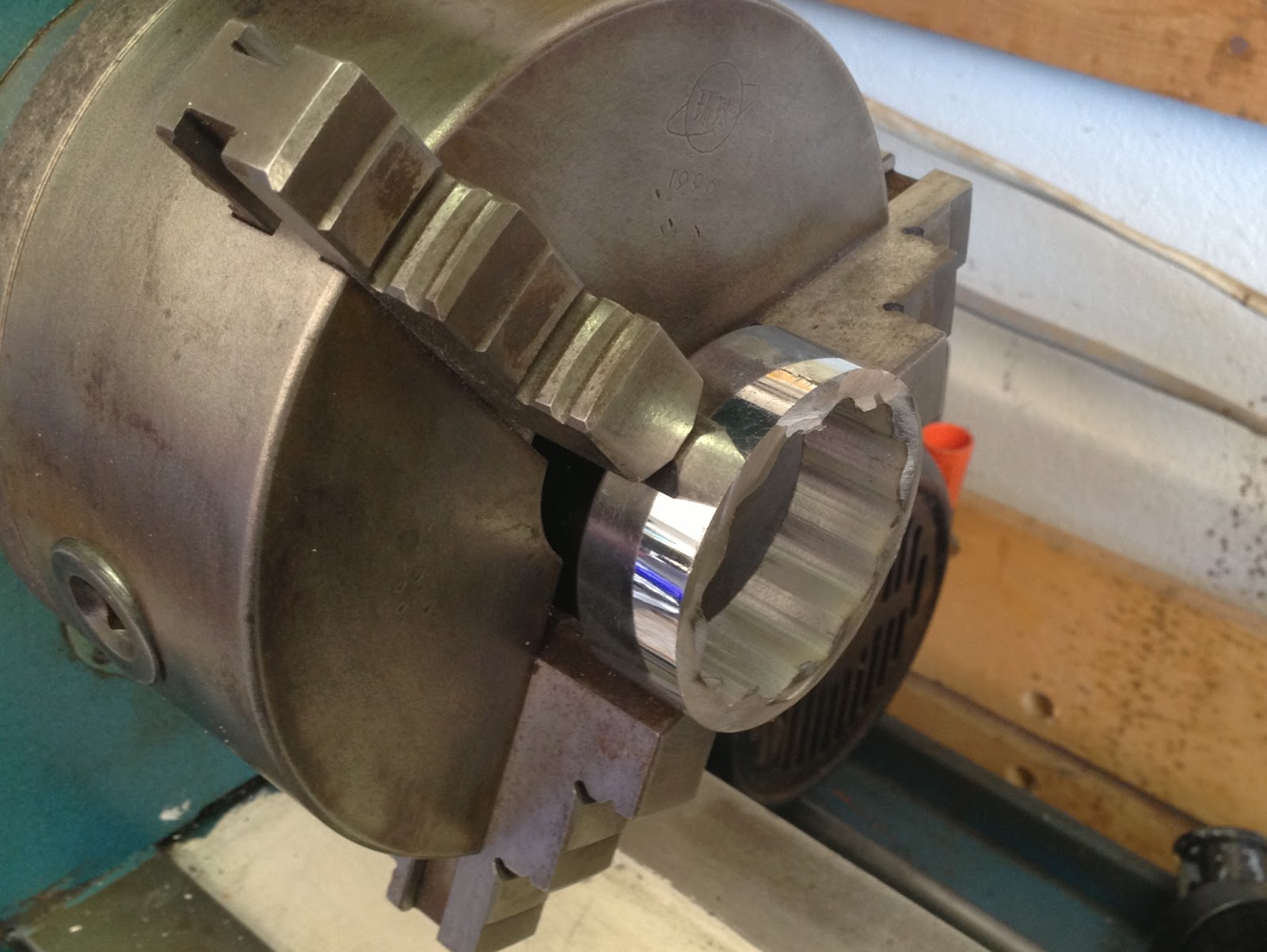
Here are the pieces laid out- one 1 and 7/8" socket; one piece 3" 3/16 wall tube x 6" long


So you lop off the Socket along a lateral point. This particular one had 2 lines around it making it pretty easy


You then face edge you cut- remember the nut you are trying to get on is only about 3/8" thick so if you don't you will either apply uneven force to the nut or not get on it solid enough to apply the appropriate torque.


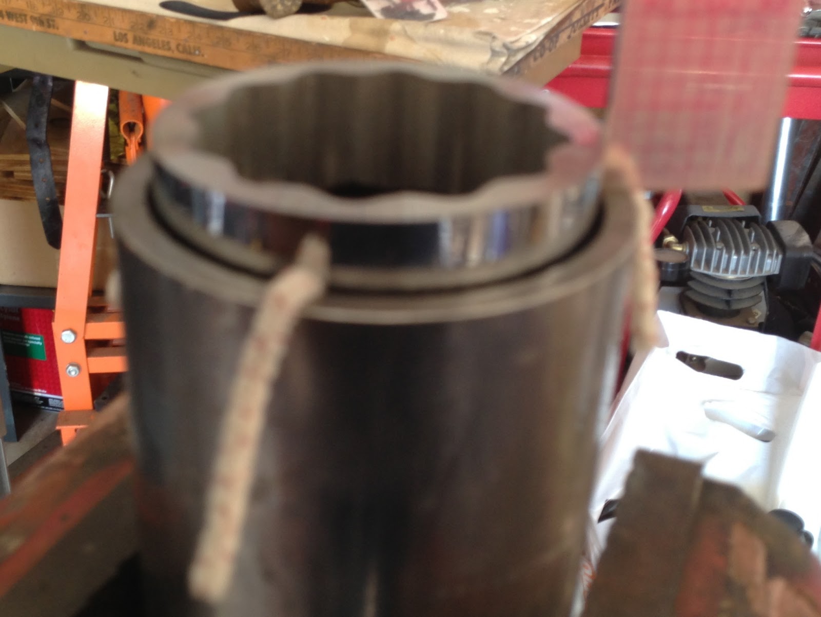
So while it's a close fit, the outer diameter of the socket is about a 1/16" smaller than the inner diameter of the tube. So- I used pipe cleaners to center the socket ends in the tube. Be sure to check that you are even around the diameter. The closer the better but EXACT does not have to be the only option


So now either put the whole thing in the toaster over in the garage (handy for this sort of thing or making a snack) if you use your wife's kitchen oven, be sure to make sure all your parts were clean 1st or A) she WiLL be pissed and B) your next couple of meals will taste funny! Heat the parts to about 350 and start to weld


Will this handle a tranny nut---yeah. Maybe over kill a bit but- hey, it only cost me $30 to make as opposed to the factory cost. One of the local Indy suppliers said he could get me one for $100.... I like mine just the same.

Sunday, March 3, 2013

Shovelhead 4 Speed Saga: Going Up Part 6

So I catch some grief for putting a speedo drive in my transmission when I wasn't going to use it to drive a speedo. It seems that unused speedo drives aren't water tight. So I found this cover set-up on ebay. I would think there is a Harley number for something similar, but I couldn't find it.


This o-ring will seal things nice and tight.


Plenty of blue loctite to seal up the threads.


It came with this stainless steel socket. If you were ambitious to make this set-up cleaner, then you should trim the overhang and get a button head screw to match.


The torn out slinger had been replaced and a new one spot welded to the clutch pushrod.


The heat and placement of the weld made the face no longer flat and square. That's a problem for bearing that needs to run here. We filed and sanded the surface flat again and socket and hammer to massage it back square.


Here's the throw out bearing stack up. Thrust washer, bearing and bushing, thrust washer, and snap ring.


Thrust washer number one.


Bearing and bushing next.


Top thrust washer.


The snap ring groove here.


Install snap ring.


Oil everything up and the shaft, too.


Slide the pushrod slinger bearing assembly into the mainshaft.


I'm not sharing pictures of the rest of the day. We went to torque the kicker shaft nut, which happens to be the part as countershaft nut and pulled the nut's threads. Déjà vu. The kickershaft threads were toast, too. It was actually lucky because somehow we had missed these nasty worn out busted up teeth on the kicker crank gear. Replacing this now will save my knee later. Back to waiting on parts.