This is where I photo document the projects I'm working on, fixing, or fixin' to fix.
Topical Link Pages
▼
Saturday, June 30, 2012
Tuesday, June 26, 2012
Monday, June 25, 2012
Don't leave gas in a stored motorcycle
Drain the carb bowl or turn the fuel off and run it dry. This is what two dirt bikes carbs I cleaned up the other day.
Completely plugged main jet.
The after picture. I took everything apart, soaked it in Chem-Dip, washed it in hot water, and blew it dry with compressed air.
The other was one was just as nasty.
Partially plugged main jet
Plugged idle jet. I didn't get an after picture, but this carb cleaned up nicely, too.
Saturday, June 23, 2012
Motorcycle Leather Hammer Hanger
So I saw a leather hammer hanger for sale and I wanted one. I had been trying to figure out how to hang hammer on bike since I saw this bike. The leather one seemed more doable for me than a welded set-up.
This project was tougher and longer than it should have been and could have bought two for cost of the tools and materials and I could have bought like five or six for the time I invested. I don't have all the steps laid out as much I would like usually show in a post because I had to back up and punt way too much on this project.
I built these little straps first.

They should have worked something like this. One for the head cover and two for the end of the handle.

Here's the head cover.

It was supposed to work something like this.

One rivet wouldn't hold this thing and I really didn't like the way the straps pulled tight. I would pull the whole dang bike to get it strapped tight, but it was still loose. I did notice that the line 24 snaps were really strong though.

This was my new concept. All snaps and no rivets and no buckles.I'm going for a longer piece to cover the handle and actually rest on the motormount to help hold it up. This one strap seems like it can almost hold the hammer by itself.
Here's how it goes snaps around the frame rail and then around the hammer handle.

Now to get to work on the big piece. Cut a big rectangle.


Layout the holes with my mock-up piece.

This wood working tool helps.

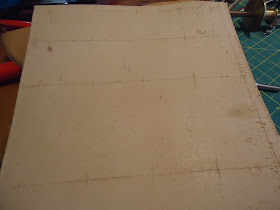
Lines marked.

Now to evenly space the snaps done the piece. About two inches.

All laidout.

Get to making holes.

Holes done and piece dyed and sealed.

All the snaps in place.

That did not fit and snap up at all. The only thing I can figure is that the 3/4 mock-up strap must have stretched easier than a 10 inch wide piece. The material thickness was about the same and snaps were placed the same. I'll remember to mock-up with the same width of material as I am planning to use.
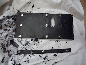
So I had to move the top half of the snaps in both of those rows. Now it fits and has speed holes. It's not quite as tight on the frame as I would like so I think I will cheat with zip ties, too.


Here's the holes for the zip ties and the old snaps.

I think a little strap on the top will help too.

Ready to go. This was ton of work and hopefully works okay. The next leather project will hopefully be easier.


This project was tougher and longer than it should have been and could have bought two for cost of the tools and materials and I could have bought like five or six for the time I invested. I don't have all the steps laid out as much I would like usually show in a post because I had to back up and punt way too much on this project.
I built these little straps first.

They should have worked something like this. One for the head cover and two for the end of the handle.

Here's the head cover.

It was supposed to work something like this.

One rivet wouldn't hold this thing and I really didn't like the way the straps pulled tight. I would pull the whole dang bike to get it strapped tight, but it was still loose. I did notice that the line 24 snaps were really strong though.

This was my new concept. All snaps and no rivets and no buckles.I'm going for a longer piece to cover the handle and actually rest on the motormount to help hold it up. This one strap seems like it can almost hold the hammer by itself.
Here's how it goes snaps around the frame rail and then around the hammer handle.

Now to get to work on the big piece. Cut a big rectangle.


Layout the holes with my mock-up piece.

This wood working tool helps.

Lines marked.

Now to evenly space the snaps done the piece. About two inches.

All laidout.

Get to making holes.

Holes done and piece dyed and sealed.

All the snaps in place.

That did not fit and snap up at all. The only thing I can figure is that the 3/4 mock-up strap must have stretched easier than a 10 inch wide piece. The material thickness was about the same and snaps were placed the same. I'll remember to mock-up with the same width of material as I am planning to use.
So I had to move the top half of the snaps in both of those rows. Now it fits and has speed holes. It's not quite as tight on the frame as I would like so I think I will cheat with zip ties, too.


Here's the holes for the zip ties and the old snaps.

I think a little strap on the top will help too.

Ready to go. This was ton of work and hopefully works okay. The next leather project will hopefully be easier.


Friday, June 15, 2012
Wednesday, June 13, 2012
Keihin CV Accelerator Pump Diaphragm
This post applies specifically to Kawasaki Vulcan with a Keihin CV carb, but is the same as a Harley Keihin CV carb.
When your carb is nasty all over the accelerator pump and no where else on the body and you notice a bit of a roll-on stumble, you need a new accelerator pump diaphragm.

Pull the carb and turn it over on the bench. These three screws hold the pump together. Remember to watch for Japanese screws.

There it is.

There's the tear. Swap it out. A HD diaphragm is the same as Vulcan or an S&S Super E.

I had to bench check it. I have bottle of rubbing alcohol I use in my auxiliary tank bottle to test bench test float heights, but I used it to check the accelerator pump function after replacing the diaphragm.
When your carb is nasty all over the accelerator pump and no where else on the body and you notice a bit of a roll-on stumble, you need a new accelerator pump diaphragm.

Pull the carb and turn it over on the bench. These three screws hold the pump together. Remember to watch for Japanese screws.

There it is.

There's the tear. Swap it out. A HD diaphragm is the same as Vulcan or an S&S Super E.

I had to bench check it. I have bottle of rubbing alcohol I use in my auxiliary tank bottle to test bench test float heights, but I used it to check the accelerator pump function after replacing the diaphragm.
Thursday, June 7, 2012
Know Your Nosecone Gaskets
Monday, June 4, 2012
Shovelhead Breather Timing with Space-N-Time Tool
The oil misting out the crankcase is just plain killing me at this point. I'm going to put the breather gear and breather gear timing to bed once and for all. I have friend that got a Delkron Time-N-Space Tool and I got a brand new S&S Breather Gear Kit.
Once you get the push rods and cam cover off, you put the this collar on the crank shaft. I'm leaving the old breather in the same spot(one tooth off mark) as an science experiment to see where it has been.

The cam jack goes on next.

Bolt it on with the gasket.

Now for the degree wheel. Oops. The front pipe needs to come off.

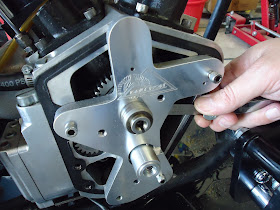
Pipe off and the wheel fits on the collar on the crank.

Find TDC on the front cylinder.

Make a point and adjust the wheel to zero, but don't turn the crank in the process.

You would think they would include a pointer with this tool kit, but a coat hanger bit works fine. EDIT: If you put pin that hole you don't need a hanger.

Now turn the motor with the primary front sprocket nut.
The basic spec is opening between 10 deg before TDC(BTDC) and 10 deg after TDC(ATDC). So let's go to 10 deg BTDC and take a look.

It is very difficult to get good pictures of the breather window with my photography skills and equipment, I but will include these pictures in this write-up to keep the processes documented even if the photos stink.
The screen is no where near the window at 10 deg BTDC.

Now over to 10 deg ATDC.

The screen is still nowhere near the window at 10 deg ATDC.

So where does the opening occur? All the way out at around at 60 deg ATDC.

The screen is coming into view.

At this point I pull out the old get and start over with the new S&S gear. As I suspected the new gear and old gear are different.
This is the new gear screen aligns with mark.

Old gear. The screen is about one tooth clockwise from the mark.

Here's the new gear in place lined up with all the marks. (The red line is a digital edit to highlight the mark for documentation clarity.)

I checked the end play to get the proper end clearance. My choice seems to be too loose or too tight. So I'll go slightly loose and it a thicker spacer than was in there from before.

TDC had to be found and wheel properly placed once again.
Check at 10 BTDC.

No screen there 10 BTDC.

10 ATDC

No screen at 10 ATDC

Where does it open?All the way out at around at 50 deg ATDC. Basically exactly where we were with the old gear aligned one tooth counterwise from the mark.

Trust me, the screen is starting into the window.

Pull off the tool and pull the breather gear. Reinstall the gear with the mark one tooth clockwise of the cam mark and we'll see how much that helps.

TDC has to be found and wheel properly placed.
Where does it open now? At around at 30 deg ATDC. So we are getting closer.

The screen is in the window.

Pull off the tool and pull the breather gear. Reinstall the gear with the mark one tooth clockwise of the cam mark and we'll see how much that helps.

TDC has to be found and wheel properly placed.
Looky, looky, at 7 deg ATDC and...

the screen in coming into the window! If I had put the old gear one tooth over the other way I bet it would have been correct.

We tried to check the closing, but we were slightly confused about what starting to close and closing meant and whether it was measured from TDC or BDC. We are going to assume the closing correct given the quality of the S&S breather gear and the Delkron case window.
A quick check on the cam end play. It's right were it needs to be.

I'm going to ahead put Harley-Davidson part number 25329-91 Air/Oil Seperator into the cam cover tube just in case.


Now I just have to put the cam cover back on. Look near the end of this post for how to do that.
The front exhaust and push rods needs to go back on, too. Read this post for that.
The misting seems better. I didn't get to run it much because I ran out of gas. The bike starts easier and doesn't seem to have the funny "catch" that it seem to have occasionally kicking through. I think that was pressure building up.
Once you get the push rods and cam cover off, you put the this collar on the crank shaft. I'm leaving the old breather in the same spot(one tooth off mark) as an science experiment to see where it has been.

The cam jack goes on next.

Bolt it on with the gasket.

Now for the degree wheel. Oops. The front pipe needs to come off.

Pipe off and the wheel fits on the collar on the crank.

Find TDC on the front cylinder.

Make a point and adjust the wheel to zero, but don't turn the crank in the process.

You would think they would include a pointer with this tool kit, but a coat hanger bit works fine. EDIT: If you put pin that hole you don't need a hanger.

Now turn the motor with the primary front sprocket nut.

The basic spec is opening between 10 deg before TDC(BTDC) and 10 deg after TDC(ATDC). So let's go to 10 deg BTDC and take a look.

It is very difficult to get good pictures of the breather window with my photography skills and equipment, I but will include these pictures in this write-up to keep the processes documented even if the photos stink.
The screen is no where near the window at 10 deg BTDC.

Now over to 10 deg ATDC.

The screen is still nowhere near the window at 10 deg ATDC.

So where does the opening occur? All the way out at around at 60 deg ATDC.

The screen is coming into view.

At this point I pull out the old get and start over with the new S&S gear. As I suspected the new gear and old gear are different.
This is the new gear screen aligns with mark.

Old gear. The screen is about one tooth clockwise from the mark.

Here's the new gear in place lined up with all the marks. (The red line is a digital edit to highlight the mark for documentation clarity.)

I checked the end play to get the proper end clearance. My choice seems to be too loose or too tight. So I'll go slightly loose and it a thicker spacer than was in there from before.

TDC had to be found and wheel properly placed once again.
Check at 10 BTDC.

No screen there 10 BTDC.

10 ATDC

No screen at 10 ATDC

Where does it open?All the way out at around at 50 deg ATDC. Basically exactly where we were with the old gear aligned one tooth counterwise from the mark.

Trust me, the screen is starting into the window.

Pull off the tool and pull the breather gear. Reinstall the gear with the mark one tooth clockwise of the cam mark and we'll see how much that helps.

TDC has to be found and wheel properly placed.
Where does it open now? At around at 30 deg ATDC. So we are getting closer.

The screen is in the window.

Pull off the tool and pull the breather gear. Reinstall the gear with the mark one tooth clockwise of the cam mark and we'll see how much that helps.

TDC has to be found and wheel properly placed.
Looky, looky, at 7 deg ATDC and...

the screen in coming into the window! If I had put the old gear one tooth over the other way I bet it would have been correct.

We tried to check the closing, but we were slightly confused about what starting to close and closing meant and whether it was measured from TDC or BDC. We are going to assume the closing correct given the quality of the S&S breather gear and the Delkron case window.
A quick check on the cam end play. It's right were it needs to be.

I'm going to ahead put Harley-Davidson part number 25329-91 Air/Oil Seperator into the cam cover tube just in case.


Now I just have to put the cam cover back on. Look near the end of this post for how to do that.
The front exhaust and push rods needs to go back on, too. Read this post for that.
The misting seems better. I didn't get to run it much because I ran out of gas. The bike starts easier and doesn't seem to have the funny "catch" that it seem to have occasionally kicking through. I think that was pressure building up.


