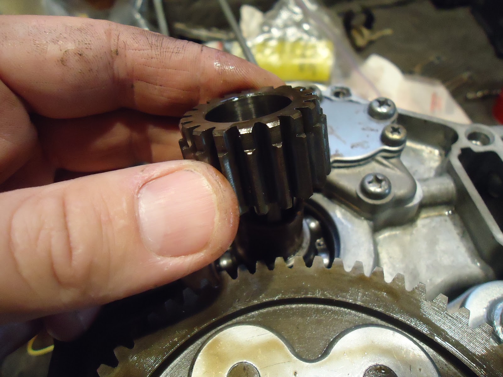
I still need to install 20, 19, 3, 2, 27(X3), and 28 to finish the clutch up. The washer(21) wasn't there when I took things apart so I didn't put one back in.

Special tab washer(20).


Castellated nut(19).

There is a special tool to hold the clutch basket to torque the castellated nut, but I don't have it. I could use my penny-on-a-ribbon to lock the gears, but the Clymers manual suggested using an extension in the wristpin bushing to hold things still.

Special socket for the special nut.

Torque to about 30 ft*lbs.

Bend up a tab of the tab washer.

Gasket(3) and Outer Clutch Cover(2). Finding the right position for the gasket is a trick.

Getting it all aligned on clutch is a trick, too.

I tore up one of these screws(27) and I thought I bought more from Dratv.com, but I didn't. Luckily I found some allen-style replacements at Ace Hardware.


Drop the bearing(28) into place and now the clutch is done.


Now the right side cover can finally go on.

Clutch cam plate(5) goes on.


Clutch lever(4) goes on the shift shaft splines and into the cam plate knotch.

"Oil through"(10) and spring(11).

Those slide into the middle hole.


Ball retainer(9) and spring(6).

The spring is under the ball retainer.

Dowel pins(19) for the outside cover.

One here.

Other one here.

New oil screen. I probably could have cleaned and reused the old one, but what the heck.

Slides into the case near the oil pump.


Gasket(2) in place.

Right side cover goes on. I already assembled 1, 14, 12, 18, 8, and 7. Check out the bottom of this post.

Two long screws(17) and six shorter screws(16).

Long ones go here.

Put the shorter ones everywhere else. Tighten all in a crisscross pattern.
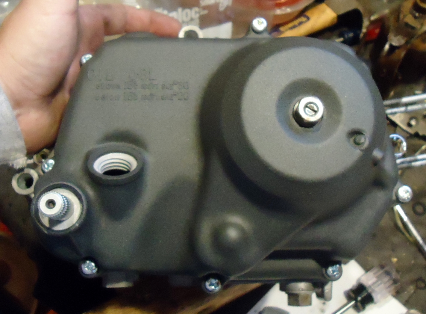
Whoa. This one bottoms out before it's tight. It's sharing a threaded hole with this case bolt. I guess my stack up tolerances got me or maybe that wasn't the correct length case bolt that I used.

At any rate a little time on the belt sander and this bolt is now the perfect length.

I thought I had a decent dipstick(3), but I didn't really. The stock is broken(right) and the junkyard special is nasty dirty(left).

Use the broken on for now and soak the better one in dawn and see how it cleans up.

Flip the motor over and install the shift shaft seal.

This is a "special 1/2 inch drive 15mm deep well seal driver."

Perfect.

Flip again and install the kickshaft seal with the same tool.

The right side is mostly done. The piston, cylinder, and head should be next.