Search

Search all blog posts here.

Search This Blog

Saturday, April 22, 2017

Finishing the Speed Dealers Customs Switchbox installation

It's time to make the connections on these switchboxes.


Yes, I am always doing things the hard way and learning what would be easier next time. So I bought 16 gauge wire and should have done 20 gauge. I'm trying to do the solder connections on the bike by myself. I'm doing a mechanical connection and solder connection with one wire that is too big. Next time, do the connections on the bench with smaller wire and better holding tools or some help.

Be sure to put the shrink wrap on the wire before soldering the joint.(That's an old lesson.)


Man this was tough and slow.


Pull the shrink wrap down.


It's always a good idea to do a buzz box continuity check on a switch once you've finished soldering the wires.


 Next lesson, don't make straight joints, I really don't like the way those will rub inside the bars. ugh.


Tried to save this switch, but getting the solder flowing and the mechanical joint apart by myself just wasn't happening. Luckily, I picked up spares of all the switches when the local Radio Shack closed up and had everything on clearance.


Fresh switch soldered up.


Shrink wrapped.


Bad picture, but I used liquid tape to cover anything the shrink wrap didn't.


The brake light connections should be easier using the Kawasaki master cylinder and switch.


Simple, like crimp and solder.


Shrink wrap.


More shrink wrap to make it less orange.


Well, this wasn't exactly thought out all the way. So I am using the Kawasaki Vulcan controls. I am a tad concerned that the customization on the clutch lever might fail. I had thought no big deal, just carry a stock style shovelhead lever with the rest of the spares. Well, the Kawasaki clutch perch is a one piece clamp and the flush mount switch boxes don't really lend themselves to quick road side swap. A roadside rig up is still possible though.


Luckily for me, Lummy showed up to help and educate me on doing the left side switches. He said don't worry about threading the wire through the hole on the tabs. Thin the wire as I had done on the right side.


Tin the wires.


So you get something like this.


Tin the terminals.


Something like this.


Now just heat the wire and terminal and everything will stick.


Cut off the extra wire. This is not as mechanically strong, but you shouldn't be yanking on the wires for the most part.


Slide up the shrinkwrap, and paint everything with the liquid tape. (Lummy doesn't slow down for pictures.)


Same process for the horn button.


Left side switches good to go. About a hour for all this work with Lummy compared to like 3 hrs for my solo work on the right side switch.


Continuity checks for all the switches in every position.

Blue loctite on all the little nuts.


Add some extension to the voltmeter wires.


I got the headlight connected to the switch. The new set up means a mess of wire connections around the top tree instead of between the tanks. I'm going to have to clean that up a bit. Then I ran out of spade terminals before I could finish up the wires, so moved on to work on the front brake and fender.


Friday, April 21, 2017

Thank you to Dropmoto.com

Huge thank you to Dropmoto.com for these Biltwell Thruster grips from last month's Instagram giveaway. I am collecting pieces for street tracker build in the near future. Follow @dropmoto for great motorcycle content and monthly giveaways.

Sunday, April 16, 2017

Centering a wheel in a Crossbones Springer

I want to start with a huge shout out to JamesD.  He brought down his wheel stand and tools and got down to business on this one.

So evidently a late model hydraulic front wheel runs the same hub and rim as a springer, but not the same offset. The axle spacing and disk were perfect, but the rim and tire were way right. Let's get started.


Here's the problem.


The 100% correct way would involve taking off the tire and using a repair manual to determine the proper offset, but we aren't going to do that. We decided to find decent spot to reference from the fender supports on each side. These wheels aren't supposed to be truly centered between the fork legs. From this point on the left, we measured as 1 and 20/32 inch to the rim.


From this point on the right we measured at 1 inch.


So we figured that the whole thing should be moved 10/32 inch to left.


Off with the wheel.


Take the caliper off, too. The wheel and tire will come off with the caliper in place and no rotor, but the goal is to get a rotor mounted after we get the wheel offset corrected.


Hang the caliper for safe keeping.


Wheel goes into the truing stand.


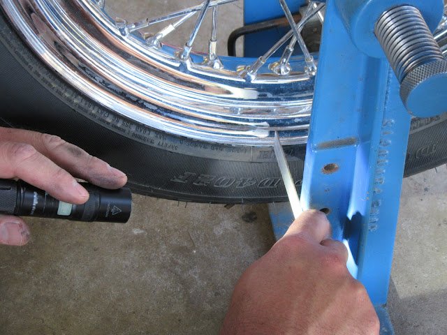
Now to get a left side reference measurement. 2 and 25/32 inches to the stand.


We did a quick true check to see how the wheel was to start with. It was within spec.


The plan is to loosen the right spokes a bit, knock the rim left a bit, tighten the left spokes, then measure. The first thing to keep in mind, righty-tighty and left-loosey, but that's easy to screw up on spokes, because it's kind of upside down and backwards. We may have tightened and not loosened the right spokes to start with, but we won't admit to it. The first try was loosen by one flat of the spoke nipple. We used the valve stem as reference to doing a revolution of the wheel.


Then some knocking.


Tighten the left spokes by one flat.


So one flat on both sides got us 1/32 of movement.

The next series we loosened two flats on the right spokes, knocked the rim to the left, then tightened the left spokes by one flat all the way around, knocked the rim to left, then tightened the left spokes by one more flat all the way around. That got us an additional 2/32 of movement, for a total of 3/32.

Another series of loosen two flats on the right spokes, knock the rim to the left, then tighten the left spokes by one flat all the way around, knock the rim to left, then tighten the left spokes by one more flat all the way around. Again we got an additional 2/32 of movement, for a total of 5/32. That should be about halfway to the goal.

So it's time to check it out on the bike


Halfway there as we thought.


Back to the truing stand. We did two more series of loosen two flats on the right spokes, knock the rim to the left, then tighten the left spokes by one flat all the way around, knock the rim to left, then tighten the left spokes by one more flat all the way around. That put us at 9/32 total or so, close enough to the 10/32 anyway.

At this point we re-trued the wheel and made sure all the spokes were tight and made the same pitch when struck with the wrench.


Install and final checks. Both sides where pretty close to 1 and 10/32 inch from the reference points.


Looking good.


Well, so much for putting the rotor on the wheel.  This rotor doesn't fit the hub. The bore in the center is too small.


Wednesday, April 5, 2017

Internal wiring for Speed Switches on the Springer Bars

Time to run the wires on this pig. I like having good distinct colors for each of my wires, but that's not easy to come by. I found an eBay source that sells some great packets though. I figured that I could use the same color on both sides of each switch on anything in the bars. Let's face it, there is going to be much of a troubleshoot on wires you can see anyway. Here's my sketch for my new wiring plan.


I still need the holes for the wires to exit the bars. That's about straight down from my bars in place.


Off come the bars.


Got to figure out the volt meter placement.


Drill some exit holes.


Drill the holes for the voltmeter wires.


The switchbox hole isn't quite right either.


Make that bigger.


That should fit just fine.


Mocked up.


Well, I was hoping to get by without slotted exit holes, but that's going to be too tight for all the wires. I think I should have gone with 18 gauge wire and not 16 gauge, but I always try to over build. It will probably bite me again when I go to solder on the switches.


Cut off dremel wheel.


Got to clean that up. No sharp corners.


Passable.


I almost forgot, I need to make another hole for the brake light wires.


Okay, here was a goofy thing I did. I bought right angle spade terminals, because I knew stock Kawasaki wires used those 90 degree terminals. Well duh, that's because the wire actually go backwards to the box. As shown below.


Well, normal straight terminals will do better for my needs. Something like this.


Better make that hole.


Centerpunch.


Drill.


Deburr and clean.


Now back to the left side of the bars. All these go through the bars.


But not through the same hole.


I couldn't find an earplug on a string, so I tried this. I used a piece of pink paracord and taped the bundle to the end. On the other end I made a knot to catch the air.


This is how I blew the cord with the wires down the tube.


It worked.


Here's the knot that did the work.


Wires through.


A bit of fishing on this end though.


Zipties so I don't accidentally pull out the wires working on something else.


Fishing two wires through the brake light wire hole was tough. I had to pull those wires through like this.


Now can I get the rest through with the first two in place? Success.


That's all of them.


Enough work for the day. Ziptie these down and work on it later.