
Wednesday, August 30, 2017
Ride in Peace - Sonny Dukes
RIP Sonny Dukes. He did a lot of photography for Easy Riders back in the day. Always cool to me, always encouraging to me about my blogging and my hack photography.

Sunday, August 6, 2017
Carb Mock-up and Throttle Cable Routing
Alright, let's figure out the carb and see if these throttle cables will work on this frontend set-up.
The intake is still sealed up from Jeff at Longbow Customs way back in December. All that has to go.

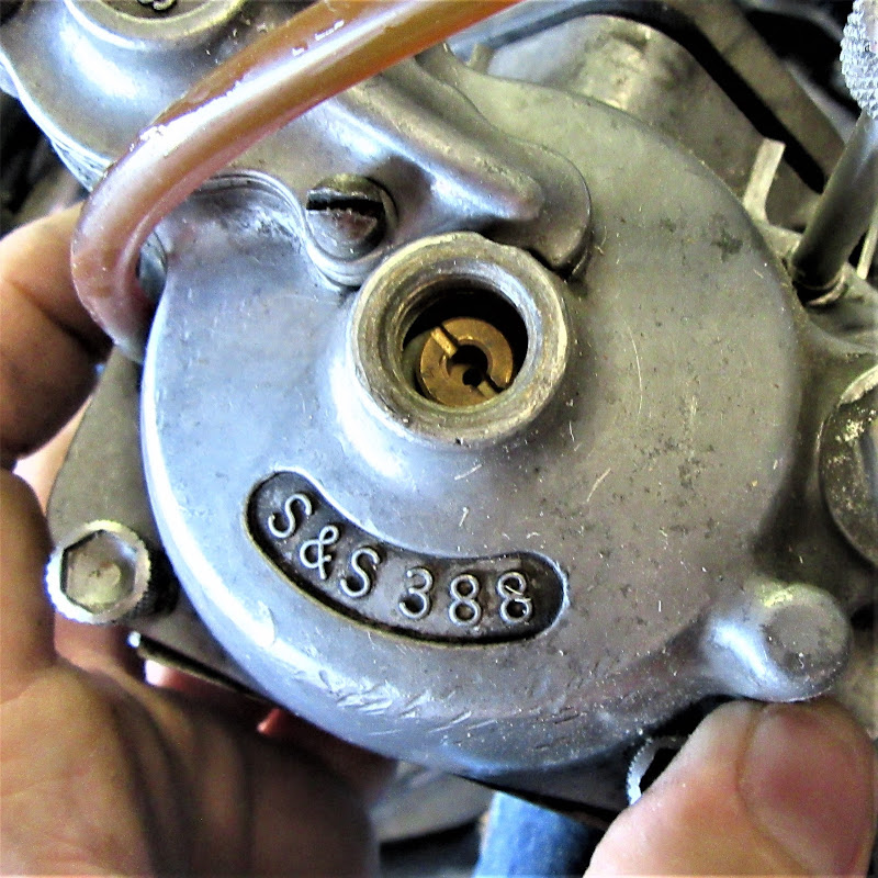
I have to take all this carb stuff out and apart to get at it.

A quick note, because I always forget, the main jet is 74.

On the hydraulic front end I was running, the cables went out, around, and through the trees to the left of the steering head. That's not really working this time.

I added this guide to the bars and it may or may not stay.

Running them on this side is getting closer to run-able.

Okay this might just work.

Final (temporary maybe?) routing, the throttle cables split over the brake line near the grip, go through the trees on the right, split around the brake again, split over the rockerbox oil line. Everything seems to work and clear all moving parts.
The intake is still sealed up from Jeff at Longbow Customs way back in December. All that has to go.

I have to take all this carb stuff out and apart to get at it.

A quick note, because I always forget, the main jet is 74.
On the hydraulic front end I was running, the cables went out, around, and through the trees to the left of the steering head. That's not really working this time.

I added this guide to the bars and it may or may not stay.

Running them on this side is getting closer to run-able.

Okay this might just work.

Final (temporary maybe?) routing, the throttle cables split over the brake line near the grip, go through the trees on the right, split around the brake again, split over the rockerbox oil line. Everything seems to work and clear all moving parts.
Front Brake Line for the Crossbones Springer with 16 ape hangers
I have already measured the extra length I need to be 6 inches longer than the hose I had. Which is odd because the stock Crossbones bars are supposed to be 12 inches and I am running 16's.
Let's get the rest of the DOT 4 out before I make another mess.

Take the banjo bolt loose to get the hose off.

Cover everything until I can get the proper hose built.

This is where my plans wrecked out again. I was planning to have a hose built locally, like before. Then, I made this discovery. The front brake line has this very specific section of hard line to route it from behind the trees and to the left of the front wheel. You have to have this section to do it correctly. A universal line won't work. Like hiding wires, just another place where a Springer is different than a hydraulic front end.

Luckily, with some internet searching, I found the part number for the 6 over line and found it available on clearance at Dennis Kirk. It was only $28 to my door. I doubt a locally made one could be had much cheaper.

I did buy fresh washer seals for the banjo bolts locally only to find the hose came with them. There were two big and two smaller ones. I used the small ones at the master cylinder and the large ones on the caliper.

Route it through.

Fit it up to the master cylinder. (I need to clean off the yucky clearcoat and put on fresh, but I want to make sure it works out first.)

The proper parts mean a good proper fit. Right in the guide and around the corner twice.

Right to the caliper.

All put together.

Torque the top banjo bolt to spec.

Wow. I never thought this would be an issue. I don't have a double hex socket in this size. I am really anal about torque in an aluminum hole and making sure it seals. Luckily my neighbor had the proper socket so that I didn't have to run to the store to get one. So that got torqued properly.

So I bleed the brake line and of course made a mess on the floor. The brake seems to function, but the lever has a ton of travel. The stock bore Harley MC is 9/16 bore = 0.563. My original plan was a 13mm Kawasaki MC = 0.512. I actually had a 1/2 in Kawasaki MC on had = .500. I will see how it goes. The bigger the MC bore the shorter the stroke needed.
I think the wiring is finished
The voltmeter is hooked up now.

This coil is wired correctly, but messy.

Much better.

The headlight feed is now hooked up.

Regulator needs hooked up.

This is a NOS Dixie regulator to go with my NOS stator.


I got Junior to help me. Just for a minute or two.

The regulator positive wire is a bit long.

Shortened with a new eye.

All wires done. Time to zip tie it all down.

Hopefully all of it works okay.

Saturday, July 15, 2017
more wires
Yeah, so, that great idea about using Kawasaki controls, because the brake light switches were so good? Well, the switch I had was bad so I had to buy one from ebay and it came with two.

I did a quick ohm check and this one works okay.

I installed it at the master cylinder to orange wires and it still worked okay. So that's a good sign.

The other nice thing about these connectors that I use is that they can be easily labeled.

Cut, strip, rosin.

Crimp and solder.

Shrink wrap and plug them in.

Now the engine cut off switch connections. These connections also allow me to bypass a bad switch on the side of the road.

The green wires go to the engine cut off switch.

All done up and connected.

One wire from the horn switch.

The horn button actually feeds a ground to the horn. So the other side of the horn button goes to the ground junction. Also, the ground for the voltmeter will connect there as well. I need a small gauge spade connector to finish voltmeter though.

Thursday, July 13, 2017
Gooden Tight Crossbones Riser Bushings Install
I hate the wiggle in the stock rubber dampened bushings of this Crossbones springer, especially running 16 inch ape hangers. So I ordered this kit off of eBay. The Crossbones with the 16 inch front tire is the same as the FLS springers, right?

I will spare you the details of figuring everything out, but no, the risers on the Crossbones and FLS springers are not the same. Notice the difference in height between the bottom hex section of the stock on the left and the FLS kit on the right.

This results in a nice tight riser, but look at all this ugliness hanging out the base of the risers. UGH.

Shopping online is not much help either. I found two different pictures for sure, but the fitment listings didn't seem to match with the correct "file" photograph. So I finally ordered by fitment and hoped for the best. Even the Alloy Art website wasn't real helpful. Basically, I discover there are three kits. One for FXS, FLS, and Crossbones; part numbers GT-FXS, GT-FLS, and GT-CBS respectively.
The packaging for the new kit confirmed this nice cut-away of the risers shown. I am still a bit amazed by these differences on the risers for each of the front ends.

Top clamp off first, of course.

These nuts next.

The old spongy rubber bushings have to come out.

Studs off next.

From my previous trials with these things, I learned to only remove one at a time. The tapers aligned everything and the top tree will shift a bit with both of them removed. It's not impossible to get things back inline, but leaving one in is easier. Unlike the stock studs, a regular 1 inch socket can be used on these.

I wasn't sure on the torque, I think I did 30 ft*lb.

Both sides done.

Bottom hard bushings go on next.

Risers on. I blew the pictures on the next steps, but the top hard bushing and sleeved metal bushing go on. Then the bolts and torque them to the same as the tapered fitting underneath.

Even when tight the risers will move easily enough to align to fit the bars.

Caps and bolts. These are easy to strip so I went gently tight and I will have to verify the exact torque sequence later.

Subscribe to:
Posts (Atom)