Search

Search all blog posts here.

Search This Blog

Saturday, November 10, 2012

Fatboy Front Wheel to Chopper Rear Wheel

This is how you make a fatboy front wheel work on the back of your choppa. The work and pictures were done by Columbus(Warpig62), but he can't figure how to blog or post pictures on the shovelhead forum. So I had to help.

First get a front wheel. $30 special right here.


U drill bit for the 7/16-16 UNC tap. 5/16 drill bit for the 3/8-16 UNC tap.


The sprocket side will be the side that sticks out more and has the lettering(if it hasn't been polished). Center up on the existing hole and drill with the U bit about 1.00 inch deep.
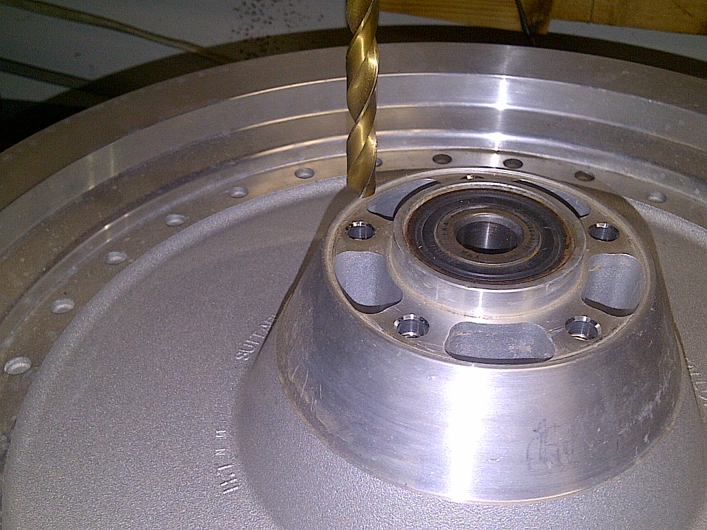


Tap the hole to 7/16-16 UNC. Had to use a very short dead center, because the drill-mill didn't have a deep enough drop.


Center up with a small drill bit for a dead center when it got deeper.


This tape is used to mark how deep to go with the tap. Should have done this before we started tapping.


Flip the wheel over to do the rotor side.


This side needs 5/16 drill and 3/8-16 tap. Keep the drill and taps straight as always.


Drill and tap them all and a front rotor goes no problem.

The sprocket side needs more attention. The spacer holes need to be drilled out 7/16 or maybe one step bigger. Paul Jr. uses a Uni-bit for everything and he's a badass builder, right?


The step on the sprocket side is about 2.300 inch so standard chain sprocket will not quite fit.


Needs to be opened up to about here.


Yes, Columbus has a mill and a lathe, but chose to go poor boy just to show a garage builder how to do it. Mark the area around the hole with red sharpie. Cover the marker with soapstone. A compass or caliper may then be used to mark the difference in the radius that's there and the one you need. This needs to done to both sides of the sprocket.


I used a dremel to remove some of the stock using the lines on both sides to gauge the depth of the cuts.
Taking your time here will pay off BIG in the end. Once you go all around, use a 1/2 round rasp to hog out the material down to your scribe lines. Once you get close, do some test fitting to ensure as exact a fit as you can.


What do you know...dang thing fits!


This choppa is going to be awesome.

Tuesday, November 6, 2012

Shovelhead 4 Speed Saga Part 2c - 4th Gear Double Seal

Here's another one of Ray's "Saddlebagrail" tricks to stop a four speed from leaking, two seals instead of one seal in the main drive gear where the mainshaft runs through the middle of it. The counterbore for the shelf is 1.250 inch in diameter and the inner diameter of the bushing that the mainshaft rides in is 1.000 inch in diameter. The counterbore is basically 7/32 or 0.21875 inch deep.


The seal is just under 0.200 inch thick.


Here's the new counterbore all the way to 7/16 or 0.4375. Again there are a lot of ways to do this depending on your skills and equipment. This was done, like my kickershaft counterbore, with a CNC mill via circular interpolation. The project would be well suited for a manual lathe as well.


Primer, retaining compound, and two seals. Use as directed.


Fancy seal driver. Once and...


again.


Sunday, November 4, 2012

CT70 Coil Fix and Engine Install

This is the view from where the engine should be looking up. Two nuts hold the coil in place.


This black wire needs to be unplugged to get the coil out to check and repair it.


Coil is out.


Here's the dratv.com boot and wire repair kit, I didn't have a boot and the wire stiff and nasty.


I cut the wire at about four inches per the instructions. (I think you could go shorter if you wanted to hide the splice.)


I figured I would check the coil now, just in case.  It seems like a coil can test good and still be bad.


Between the black lead and the ground. I get 2.6 Ω, may be high, but close enough.


Now I'm highly confused the manual said 9 to 10 Ω from plug wire to ground, but what  I actually from is 9.6 kΩ from plug wire to lead wire. I'm going with it, because I don't really trust the manual, but if it doesn't through spark I will plug the coil from my other CT70.


Lay out the splice pieces.


On the coil wire.


On the new wire.


Coil going back to its home.


Route the wire out.


Motormount bolts.


Short one here.


Long one here.


Crankcase breaker hose.


Heave it in.


Back and realize this won't fit. Custom parts, custom problems.


And the hose clamp if junk, too.


I'll try to make it work.


Engine is in the frame.


Fill with 30 weight.


The dirty dipstick cleaned up nicely.


Gap the spark plug.


Install plug.


Figure out how much wire I need.


Cut to length install boot.


Looking good.


Well I did have to start getting parts off of the other bike. I thought I had a key for this one, but I didn't and the switch looked too jacked to get a key for too. So I pulled the ignition switch from the other bike hung it back here for now.


I think I cut a groove in the base get this to fit okay.


Now try this.


No that still doesn't fit. I'll buy the 45° version.


Here's my busted bar. I'll put it back on, because the throttle and cable are still good. I want run this motor, before I spend more on redoing everything else.


Seal here.


This notch with the ramp.


lines up with this screw.


I'm not sure why I can't get this boot to get on the top, but hopefully that isn't a real problem for now. I will be getting a new throttle cable soon.


Mock up the exhaust pipe.


Put the exhaust gasket on.


Bolt up the pipe this time. When I get the shocks sorted and go back up, I will then see which pipe is better and most like have to straighten it out to fit good.


I have a battery and IV gas can, but I'm done today. I don't want to get angry when it doesn't start right up today.