
Here's the first panic of the day. My universal gasket kit had this wrong, but close, base gasket.

Luckily, I little more digging through the gaskets and I found the correct base gasket(4).

A little pre-planning and checks first. So here's my the seals, gaskets, and parts that will need to do the job.

This is the top of the piston. One book and dratv.com say point the arrow. It seems odd, because that means the bigger valve cut away is with the smaller exhaust valve.


Okay this is where things got out of sorts the first time I put this together. One books shows this and I couldn't find anything else at the time. The rings I had were square and black and double beveled copper color with silver edge. I compared the rings on my old piston and the beveled ring looked to be the middle ring. I was wrong.


I put the whole topend together and then I found the proper instructions with pictures on dratv.com. I stole them and put them on here. Hopefully they don't get upset about that. I spent a lot money with and give a lot of free ad space if anyone is following this build. Also I didn't document my re-teardown and second build-up so if you see the rings wrong in the rest of my pictures know that it's been taken care of.


Okay, back to my work and pictures. Install one wristpin keeper. These are always a trick.


Base gasket(4) and dowel pins(14) go on.

Moly grease into the rod bearing.

Assembly fluid on the wristpin.

Wristpin into piston from the side without the wristpin keeper. Just enough to stickin through to caught the rod bearing.

Line it all up.

Push it in. It's tight, but once it starts to move it will go fast.

C-clamp and sockets squish it in the last little bit.

Go deep enough to find the other wristpin keeper groove.

Work in the other wristpin keeper.


Oil seal(10) goes here.

Oil up the piston and rings.

The book said the rings could be pushed together and the cylinder(3) installed by had without a compressor and it actually worked.

Cylinder(3) on.


Holder bolt(9) goes here.

Camchain diagram.

New parts. Camchain(2), and rollers(4 & 12).

Camchain routing starts here.

Routes through here.

Roller(4) goes here.

Roller(12) goes here.

Funny bolt(13) and washer(19).

They go into this hole and through the roller(12). The chain runs on both sides of that roller.


Notice the piston at top dead center(TDC) and how the keyway on the crankshaft lines up to it.
This how you find TDC when the rotor is not installed.


Back to the first diagram. Headgasket(6), dowel pins(15), and oil seals(12 & 10).

Moly grease on all the cam and contacting surfaces.


Cam goes into the head. I had to pull the tappet covers and tappet adjusters to get it to find its home.

Now to the camgear(1 on the camchain diagram). Notice the "O" mark the lines up with the "lonely" hole and is perpedicular to the center line of the inline wholes. That is the TDC mark for the cam and camgear.

It should be inline with the keyway of the crank.

Position the cam in the head to match the thread holes to the holes of the camgear.

Slide gear and chain into the head and the head onto the cylinder studs and cylinder.

Another keeper bolt.

Adjust the TDC marks and install all three the camgear bolts.

Head cover diagram.

Gasket(5).

Cover(1).

Nuts and washers. I'm not sure exactly why, but the acorn nuts go with the steel washer and the regular nut goes with the copper washer. The regular nut and copper washer go on the bottom right(looking from front).

The regular nut and copper washer go here.

The acorns and steel washers go everywhere else. Crisscross torque pattern.

Long cam cover bolt. Goes in...

and through.

The tab on the camcover goes between the two tabs in the head on right.

Gasket and camcover go on and the long bolt threads into it.

Looks a little more like a motor now.


Spark plug wire guide goes here.

Camchain tensioner diagram

New number 11.

Looks better than the old one. Put it into number 8.

Slide that assembly into the case.

Add 6, 10, 18, and 16.

Looking good and holding things tight.

Generator/ignition diagram.

New o-ring(16) and seal(15) for the stator plate.


These caulk spots are sealing though holes.

New little o-rings(17).

They go here.

The plate goes on like this. There is an upside and a downside be careful.

ACE Hardware replacement screws again.

Four long screws(20) hold the stator coils(11) in place.
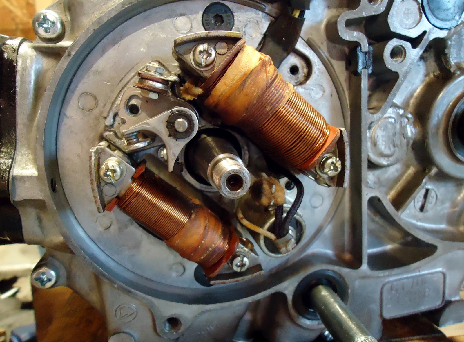
A screw(19) and washer holds the condenser(4).

A screw(19) and washer here for the points breaker(2). I'll adjust that later.

A screw for this clip, too.

Key goes in the keyway.

Rotor(9), washer(14), and nut(26) go on.
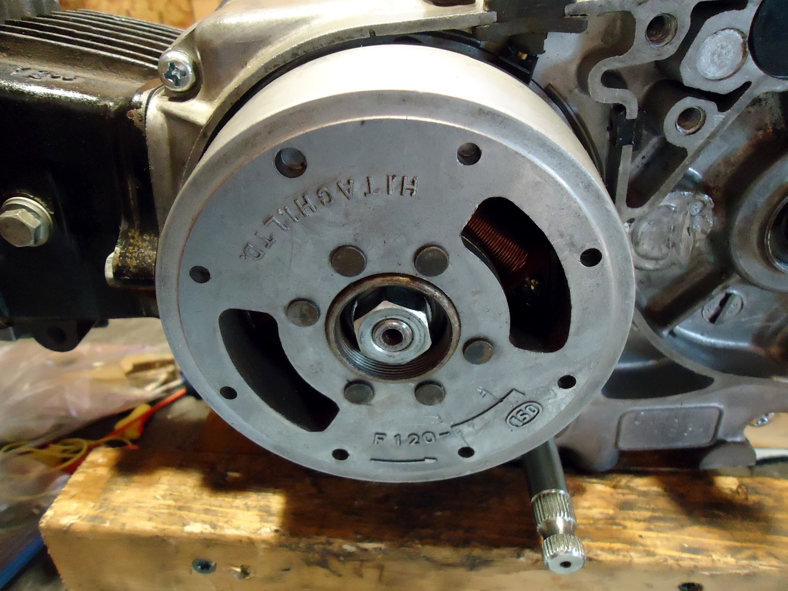
Hold the rotor and torque the nut.

Getting there for sure

Great blog! Going to rebuild a 70cc engine myself, this will be very helpful!
ReplyDeleteYou put the copper washer on the wrong stud, stud. It seals the upper end of the cylinder stud that the oil flows to the can area. Bottom left looking down from in front, same as that little o-ring you placed in the head gasket.
ReplyDeleteHi I do have engine ct70 bore 70.can I replace the bore and piston to 90 cc
ReplyDeleteAwesome job
ReplyDeleteOk , i just stuck an 88 cc race head and cylinder kit on my trail 70 and it is leakibg oil out of the right lower cylinder base area, why?
ReplyDeleteNvm. Loose clutch cover , oops
ReplyDelete