
It needs to be right about here, so I need a new backing plate for this.

Take it all apart.


This bolt got loose at some point before I owned this bike. The sides are not parallel and it's pretty much a bandaged together junk anyway.

I traced a template to keep notes on.


Lots of reverse engineering going on.


And here are my notes.

I used DraftSight to make a drawing. This is the original plate layout. The properly scaled .pdf is here.

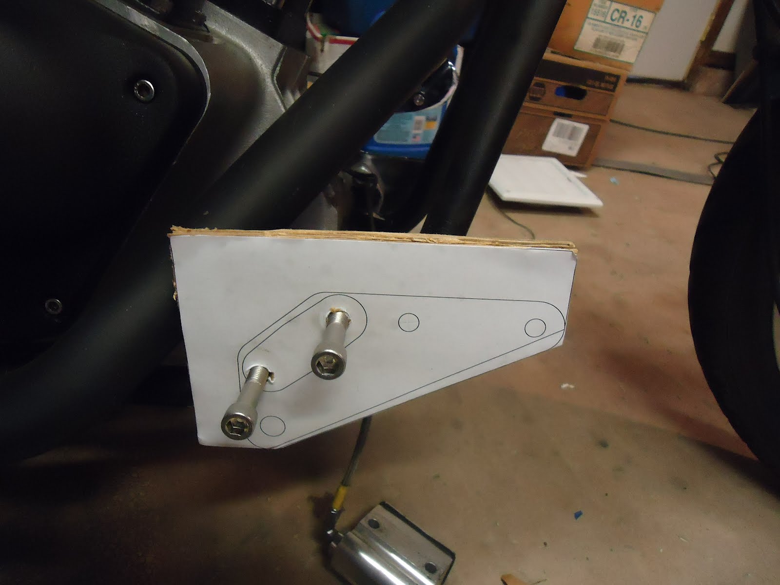
This is what I figured the first mock-up would look like. Again .pdf here. I had planned to move the master cylinder and lever mounts(digitally) up and back to match the new peg location, but the location of the frame tab made that not possible. I might have done all this with a transfer punch and skipped the cadwork, but I didn't know until I drew it.

Here is my print out and cardboard for my first build.

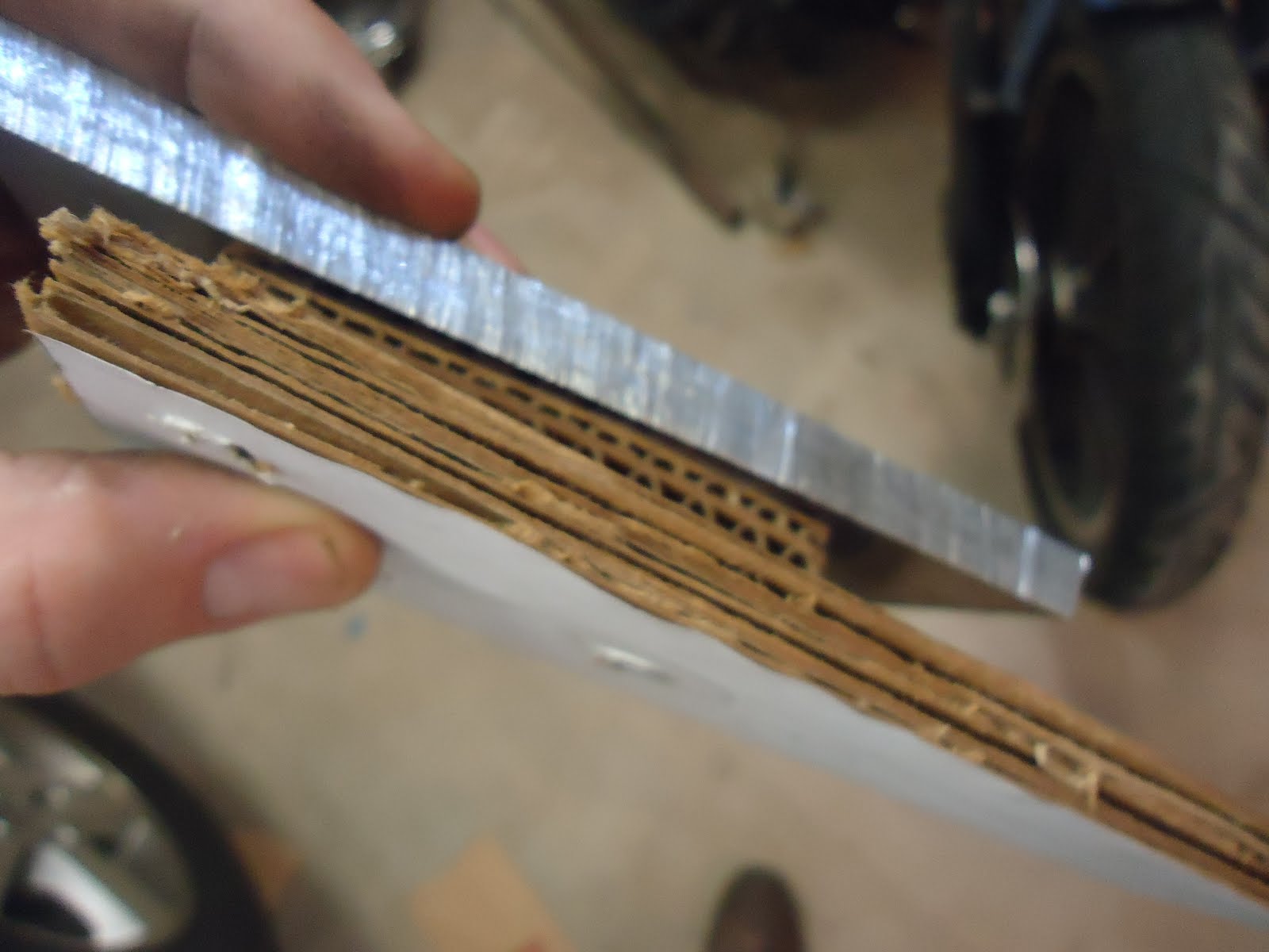
About three layers of this cardboard matches the thickness of my aluminum plate.

I glued up two of these to play with. I know I need a spacer, too. So I got those glued up as well.

Good thing I made two I screwed this up by cutting on the wrong line.

Cardboard mock-up.
I think I need to move the back line forward about an 1/8 of an inch to clear the pipes.

Here's my final drawing and the .pdf is here.

Time to get to real business.

I used some layout dye to be able to mark the outline in case my template comes off in the middle of working.

Rubber cement should hold the template to the metal, but I'm just guessing and would call it experimental at this point.

I center marked the holes on the drawing.

So center punching the holes is super easy.

Ready to make some chips.

Sawzall works pretty, but I still need a bandsaw.

Now to drill the spacer.


I went to check out my hole spacing on the bike and of course, I left too much material around the holes.

Second cut and my hole spacing looks good.

Now to put a paper copy of the plate on the spacer see if it fits. The plate as drawn clears the pipes, but the nut on the back for the pegmount won't.

So I tried the metal spacer, a cardboard spacer, and my original cardboard plate.
That clears everything and actually the extra spacer pulls the peg mount out to about the right width to match the other side.


I heard canning wax will help with the saw, but I'm not sure.

I just transfer punched my second spacer.


Looks good.

I drilled the plate and everything works together so far.

It all mounts and clears.


Finish the remaining holes in the plate.

Check the master cylinder holes and they fit.

I like the peg mount hole.


Lever hole is good, too.

Nut for the lever clears everything.

Hack off everything that doesn't look like a backing plate.

To the belt and disk sander with everything.


I bolted the spacers together and hacked them down and sanded them pretty.

The paper and rubber cement worked and peeled right off when I was done. I would call that a success.


New bolts from Ace Hardware.

On up with it. The brake lever is now too low, but a longer plunger will make it work.

I got a longer bolt.

Cut off the head and rounded the tip.

Works.

The lever is bit forward. The heel of my boot want to come over the peg when I go full on braking. I'll try it this way for a while and I have another piece of aluminum if I need a new lever.

It will be better with some powdercoat, too.


No comments:
Post a Comment